4.4 USE OF THE AUTOMATIC CLAMP - OPTIONAL
Keysarettedintotheclampautomaticallybymeansofamechanicalloader.Thekeysarepositionedontheir
back and automatically locked. Keys are secured by the clamp jaws, which are powered by a motor incorporated
in the clamp. This excludes any operator interference.
NOTE: never use pins with the Automatic Clamp.
ATTENTION: only for keys with cuts on 1 side and key stop. NO keys with plastic heads
(except for SWING and SILKY), no cruciform keys or keys with tip stop.
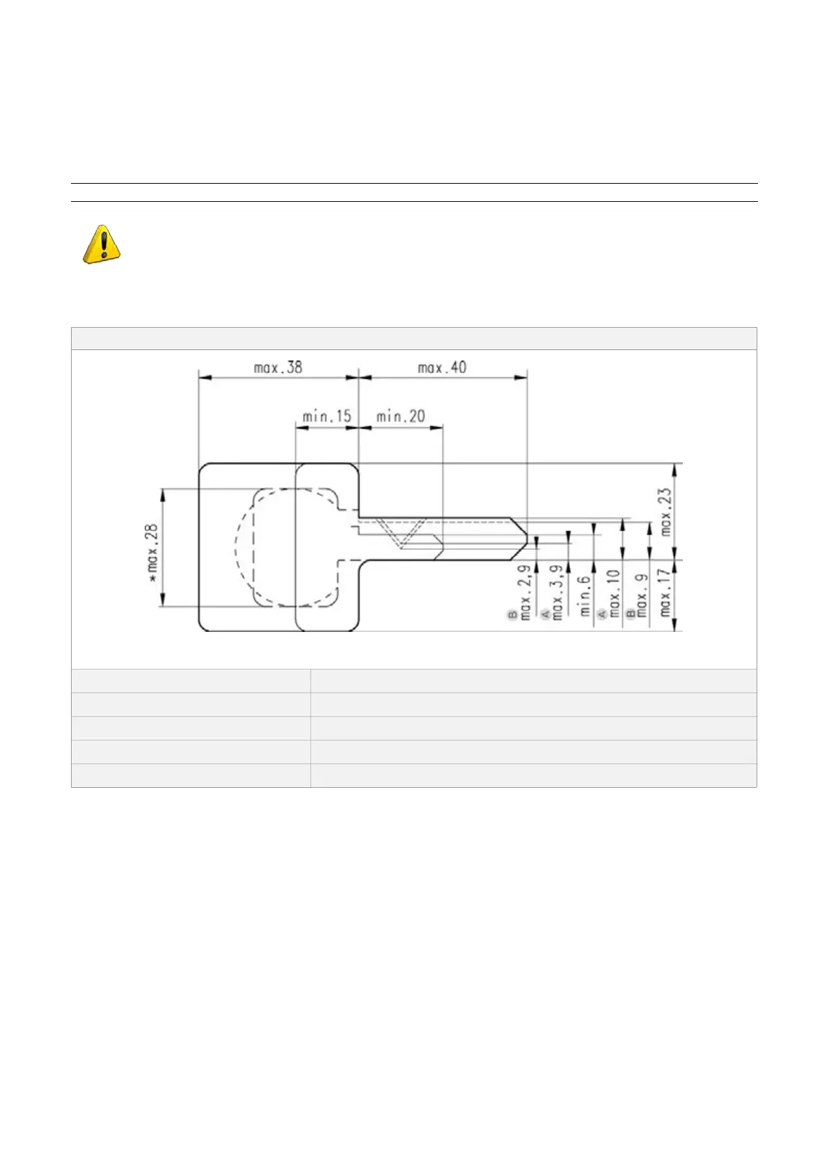
Keys cut on this clamp must be of the types described below:
TECHNICAL DATA FOR KEYS TO BE CUT
Fig. 27
Key thickness min.1,8 mm - max.2,6 mm (with jaws A or B)
min. 2,0 mm - max.2,8 mm (with jaws A + 2,0 ÷ 2,8)
Max. cutting depth: 3,9 mm (with jaws A); 2,9 mm (with jaws B)
Blade height/width: max.10 mm (with jaws A); max.9 mm (with jaws B)
Key head width: *max. 28 mm
1) Jaws A (standard) (Fig. 28)
• Automatic Clamp (L1): with jaws A
• Reading standard Clamp (L100): side A
2) Jaws B (provided) (Fig. 29)
• Automatic Clamp (L1): with jaws B
• Reading standard Clamp (L100): side B
3) Jaws A (lower) + 2,0÷2,8 (upper - provided) (Fig. 30)
• Automatic Clamp (L1): A (lower) + 2,0÷2,8 (upper)
• Reading standard Clamp (L100): side A
Operating Manual UC199
Copyright Silca 2012
20