7.13 MOTOR REPLACEMENT
1) turn the machine off and disconnect from the power supply.
2) gain access to the top compartment (Ch. 7.3).
3) gain access to the bottom compartment (Ch. 7.4).
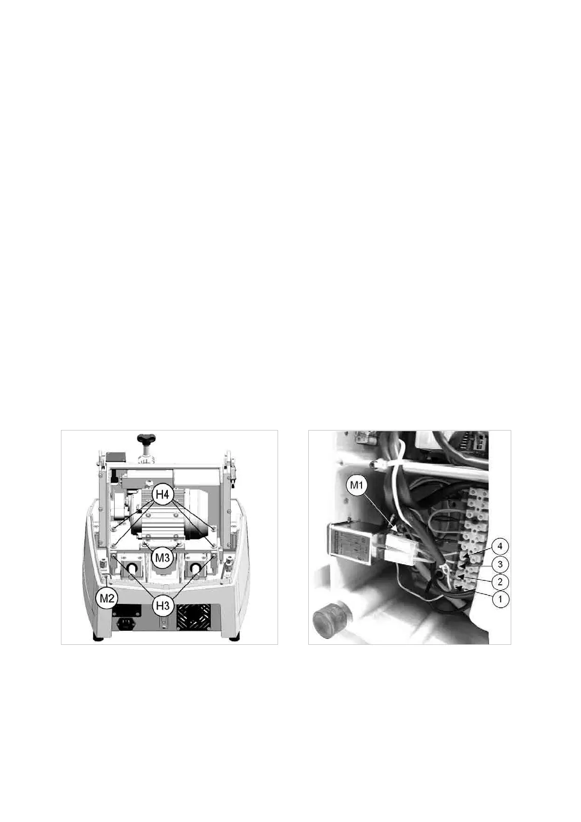
4) disconnect the 4 wires (1, 2, 3, 4) on the motor from their connections (Fig. 97).
5) loosen the nut (M1) and remove the earthing wire.
6) place the key-cutting machine in position on the work bench.
7) loosen the wiring clip (M2) (Fig. 96).
8) loosen the 2 belt tightening screws (H3).
9) loosen the 4 screws (H4) on the motor support plate and remove the unit.
10) loosenthe4motorxingscrews(M3)andremovethemotor,takingcarewhenpullingthewirethroughthe
wiring clip.
11) loosenthe2motorpulleygrubscrews.Removethepulleyandttothenewmotor.Securebytighteningthe2
grub screws.
12) tthenewmotorontoitsplateandsecurewiththe4screws(M3).
13) tthemotorplateintoitsseatandtightenthe4screws(H4)withoutlockingthem.
14) tthebelt.
15) tighten the 2 screws (H3) until the belt is properly tightened then lock the 4 screws (H4) on the motor support
plate.
16) carefully take the motor wires through the wiring clip, then tighten.
17) place the machine on its right-hand side.
18) Connect the 4 motor wires (1, 2, 3, 4) and earthing wire.
19) repeat the above operations in reverse order to gain access to the bottom compartment.
20) repeat the above operations in reverse order to gain access to the top compartment.
Fig. 96 Fig. 97
Operating Manual UC199
Copyright Silca 2012
84