7.11 SENSORS REPLACEMENT
X AXIS SENSOR REPLACEMENT (CARRIAGE SENSOR)
1) turn off the machine and disconnect from the power supply.
2) gain access to the bottom compartment (Ch. 7.4).
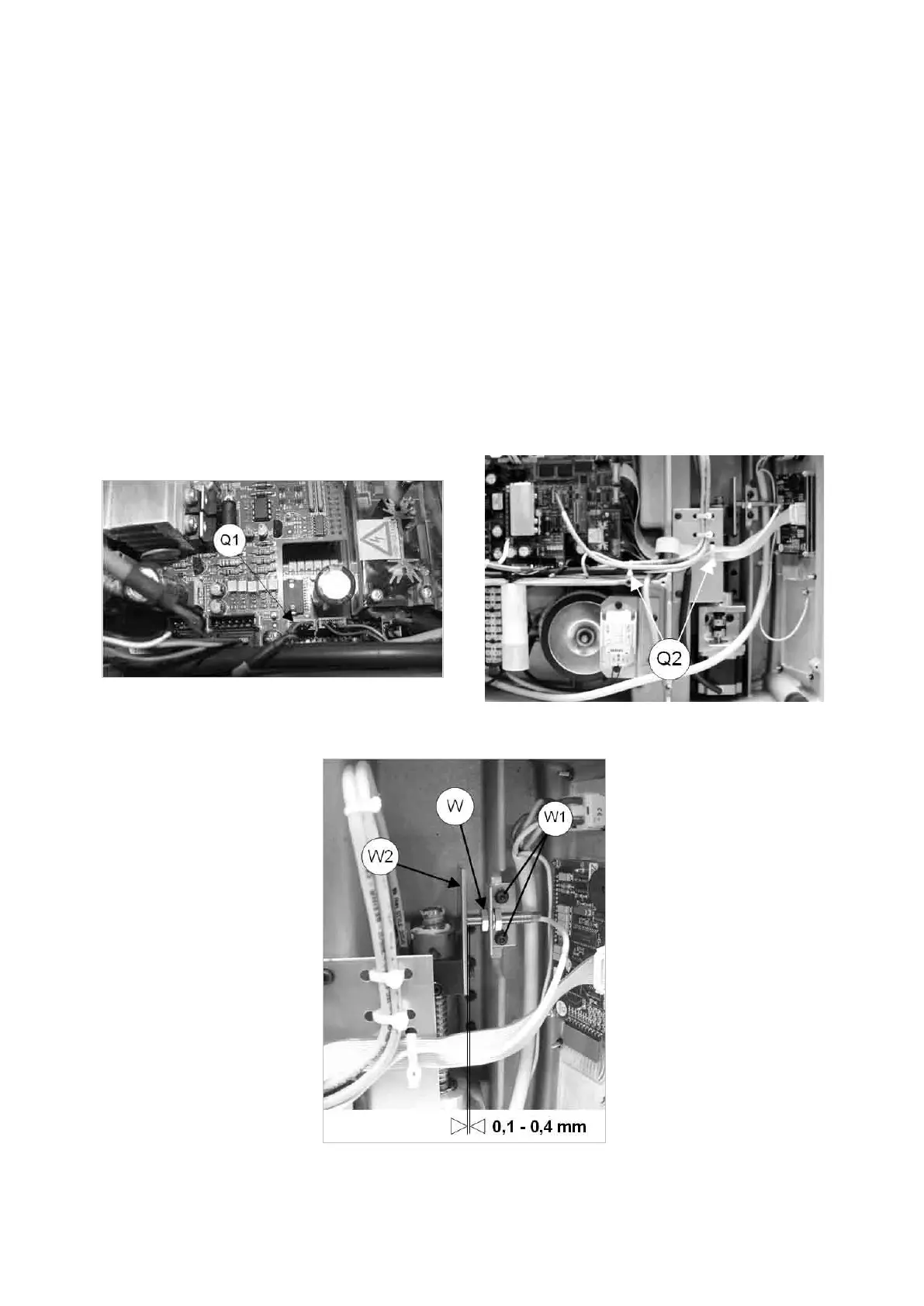
3) use the pliers to disconnect the X axis sensor connector (Q1) from the board (Fig. 88).
4) cut the 2 wiring clips (Q2).
5) loosen the nut (W), loosen the 2 screws (W1) and remove together with the sensor and its support (Fig. 89).
6) remove the faulty sensor from its support and screw in the new one, then secure the support with the new
sensor by tightening the 2 screws (W1).
7) place the new sensor in position by screwing it down until it almost touches the bracket (W2) (Fig. 89) then
secure with the nut (W) and lock nut.
8) connect the sensor connection (Q1) to the board and secure the sensor wiring with a new clip.
9) proceed to Maintenance > Machine zeroes (Ch. 5.8.2).
10) replace the bottom plate.
Fig. 88 Fig. 89
Fig. 90
Operating Manual UC199
Copyright Silca 2012
80