5.8.2 MACHINE ZEROES
The machine is pre-arranged for a partial “self-setting” system by means of templates provided (Ch. 1.6) and
specicprocedures.Theseproceduresmustbecarefullycarriedoutfollowingthedescriptionsandillustrations
indicated below.
EVENT
MACHINE
ZEROES
CALIBRATIONS
STANDARD
CLAMPS
AUTMATIC
CLAMP
Electronic board replacement
NO YES YES
Replacement of the Optical Reader unit
NO YES YES
Replacement sensors
YES YES YES
Replacement of the cutter shaft (*)
YES YES YES
Replacement of the ball screws (*)
YES YES YES
(*) Only from Silca S.p.A. or Silca Authorized After-Sales Service Centres.
2 – MACHINE ZEROES
NOTE: this operation is possible only with standard 4 sided clamps.
NOTE: If the machine has an optional feeder unit installed, proceed as follows (see Ch. 5.8.3):
1) Remove the Automatic Clamp: loosen the screw (D2) and pull out the clamp to the left.
2) Remove the Loader: possible only after having removed the automatic clamp; loosen the screw (D3) and pull
out the loader.
NOTE: the machine is used without the loader unit, remember to insert the serial protection (S1) into
the special loader seat, then t the standard cutting clamp into the special dovetail runner and push
all the way in to the right. Tighten the screw (D2).
With the pointer on position 2 - press ENTER
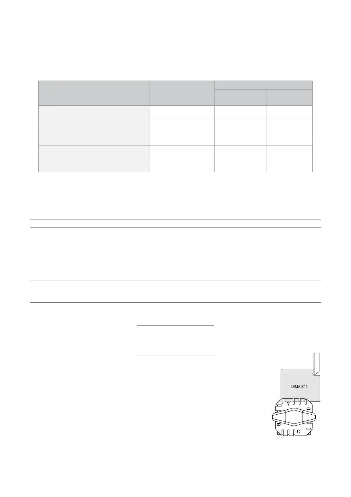
Install Z19 template
cutting side
See operating manual.
[ENTER]
-
tthetemplateZ19onsideAintotheL100Standardclamp(cuttingside).
-
press ENTER, the display will show:
Move axis up until
contact is made.
See operating manual.
[ENTER]
Move the X and Y carriages by hand, to take the template Z19 up against the cutter to make
contact with the side and front (Fig. 62).
Fig. 62
cutter
clamp cutter side
Operating Manual UC199
Copyright Silca 2012
56