4.5 USE OF LOADER - OPTIONAL
After installation of the Loader Unit (ch. 4.7), when placing key blanks into the loader, to ensure proper operation
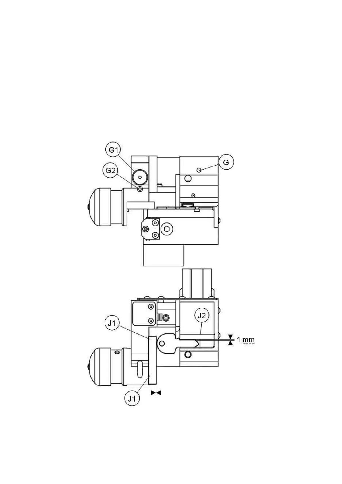
of the mechanical parts of the device, remember the parameters highlighted in Fig. 27, and pay attention to:
• Orientation of the key
• Stem dimension regulation
• Head dimension regulation
1) The keys must be placed into the loader with the head to the left and the back to the operator.
2) Adjust the screw (G), place the plate (J2) against the stem of the key, then draw back by about 1 mm.
3) Loosen the screw (G2) adjust the screw (G1), place the magnet plate (J1) against the head of the key. Tighten
the screw (G2).
Fig. 31
Operating Manual UC199
Copyright Silca 2012
22