1.1 MAIN CHARACTERISTICS
• Movements
The2axes(X-Y)moveonballscrewsactivatedbystepmotorsonrectiedrollerguidesandballbushes.
• Clamp
Standardfour-sidedclamp,speciallydesignedtogripmostatkeys.
• Working tools
Consists of a cutter in hard metal (carbide), that is easily replaced. Suitable to the type of work and speed rotation
needed.
• Display
Rear-illuminated and placed on the front of the machine.
Display with 4 rows of 20 characters each.
Its technical features and positioning make it highly practical in use.
• Laser reader
Designed to read cuts on keys to be reproduced
.
LOADER UNIT - OPTIONAL
• Automatic Clamp
Only for keys as in Fig. 6.
• Loader
Only for keys as in Fig. 6.
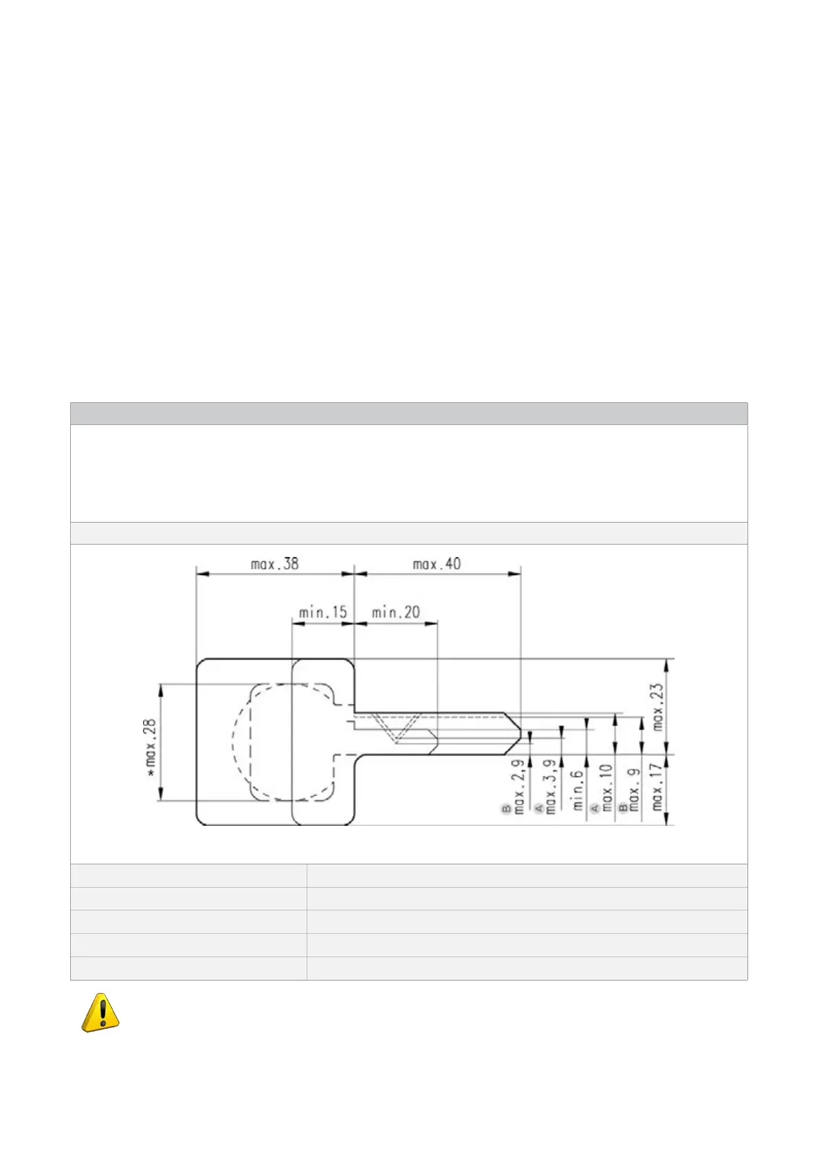
TECHNICAL DATA FOR KEYS TO BE CUT WITH OPTIONAL FEEDER
Fig. 6
Key thickness: min.1,8 mm - max.2,6 mm (with jaws A o B)
min. 2,0 mm - max.2,8 mm (with jaws A + 2,0÷2,8)
Max. cutting depth: 3,9 mm (with jaws A); 2,9 mm (with jaws B)
Blade height/width: max.10 mm (with jaws A); max.9 mm (with jaws B)
Key head width: *max. 28 mm
ATTENTION: only for keys with cuts on 1 side and key stop [not keys with plastic heads
(except for SWING and SILKY), not cruciform keys or keys with tip stops].
Operating Manual UC199
Copyright Silca 2012
5