Press ENTER, the display will show:
Pos. sensors
ICX=ON ICY=ON
See operating manual.
[ENTER]
If this does not occur and the status of one or both is OFF, taking due care (the machine is live), proceed as
follows:
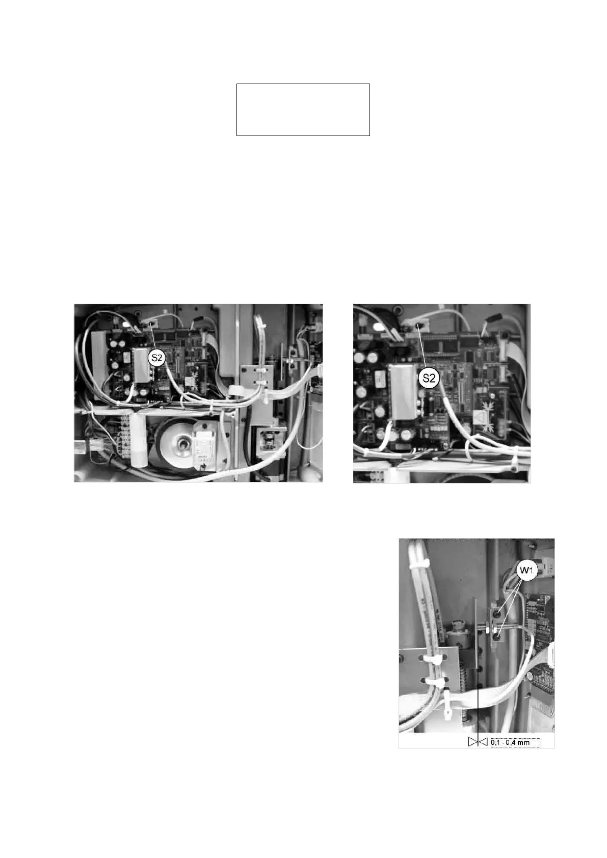
REGULATION OF THE Y AXIS SENSOR:
1) Without disconnecting the power lead, gain access to the bottom compartment (Ch. 7.4).
2) Loosen the screw (S2) and move the sensor support by hand until the point at which OFF goes to ON is
found.
3) Lock the sensor support in place by tightening the screw (S2) (Ch. 7.11).
4) Secure the bottom plate with the 8 screws (V1) then re-position the machine on the work bench (Ch. 7.4).
Fig. 63
REGULATION OF THE X AXIS SENSOR:
1) Without disconnecting the power lead, gain access to the bottom
compartment (Ch. 7.4).
2) Loosen the sensor support plate screws (W1) (Fig. 64) and move the
plate by hand until the description on the display goes from OFF to ON.
3)
Secure the plate by tightening the screws
(W1) (Ch. 7.11).
4) Secure the bottom plate with the 8 screws (U3) then re-position the
machine on the work bench (Ch. 7.4).
5) When regulation of one or both the axes is completed, press ENTER.
Fig. 64
Operating Manual UC199
Copyright Silca 2012
57