1-4
Network configuration, continued
Connecting
network loops
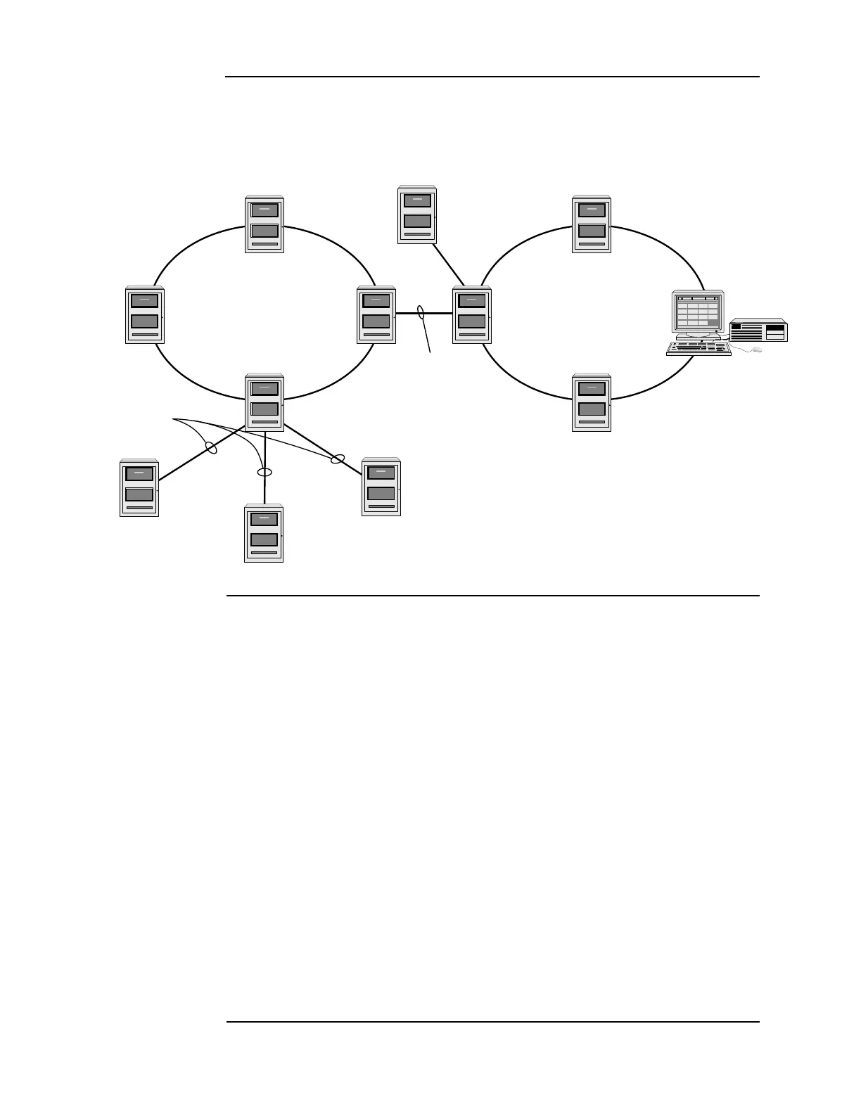
Network loops can be joined by using physical bridge cards. There may be no more than two
Style 7 network loops, two hub configurations, connected in tandem. For every two loops that
are interconnected using one physical bridge, there can be a maximum of three physical
bridges used in a star configuration. See Figure 1-3.
Figure 1-3. Interconnected loop configuration
Network
communication
Network communication is achieved using the 4010-9902 and the 4010-9922 NICs. Each
network node requires a NIC. Once the FACP is a network node, it may be programmed to be
fully in control of other nodes, to be fully passive, or anywhere in between.
The 4010-9902 and the 4010-9922 NICs are option cards that use a PDI connector to
communicate with the CPU. The NICs allow for communication between each panel using a
fiber or twisted shielded pair wire in a Style 4 or Style 7 wiring configuration.
The NICs are designed to be connected in a point-to-point arrangement, so that one wire fault
does not cause the entire system to fail. The point-to-point arrangement provides the most
secure and fault-tolerant wiring possible.
Two types of media cards can be used with the NICs:
• The Fiber-Optic Media (4010-9819) card can be used for electrically noisy environments,
or for connecting externally to other buildings.
• The Wired Media Card (4010-9818) is used in all other types of applications.
Up to two media cards can be plugged into each NIC. The same NIC can use a combination of
different types of media boards; for example, a NIC may have a Wired Media card connected
to the left port, a Fiber-Optic Media card connected to the right port.
For setup and installation of a physical bridge card, refer to document 579-184: 4100/4120/
4010-Series Physical Bridges and Media Modules.
For setup and installation of network interface cards, refer to document 579-956: 4010ES
Network Interface and Media Card Installation Instructions.
Remote Loop
Physical Bridge Link
Local Loop
Physical Bridging
(Star Configuration - 3 max)
TSW
Physical
Bridge
Link
Physical Bridge Links
Hub Node
Hub
Node
Remote
Node