5-13
Installing the optional modules
Overview Note: Skip this section if no optional modules need to be installed.
This page contains the general placement guidelines for the optional modules that can be used
with the 4010ES panels. If this information conflicts with the installation instructions for the
optional modules, the installation instructions take precedence. Refer to Table 4-3 in Chapter 4,
“Orderable panels and devices,” for a list of these installation instructions.
In addition to basic system components, the 4010ES panel has space on the PDI to
accommodate the following option card configurations:
1. One Two-Block 4 inch x 10 inch option card (such as a NIC or a SafeLINC card) and one 4
inch x 5 inch option card.
or
2. Three 4 inch x 5inch single-block option cards.
If the system is a two-bay system, an eight-block PDI card in the second bay allows for
additional mounting space beyond the three blocks in the top bay.
Note: Some systems come with option cards pre-installed. In these cases, the number of available option
card blocks is reduced. See the PID list table in Chapter 4 for details.
Installing one-
block and two-
block cards
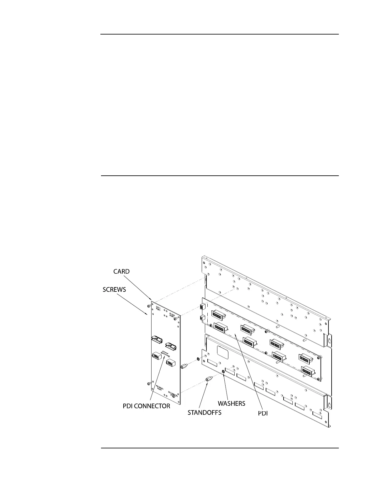
The PDI cards are mounted to the back of each bay and carry power and data across all bays.
Use the following instructions and Figure 5-13 to mount cards into a 4010ES panel bay
1. Screw standoffs and washers to the appropriate holes in the back of the cabinet. These holes
must line up with the screw holes in the card.
2. Plug the card into the appropriate blind mating connector. Seat the card firmly onto the PDI
when installing to ensure complete insertion of the power connector into the PDI.
3. Secure the card to the standoffs with screws and washers.
Figure 5-13. Card connection to a PDI