6-8
MSS IDNet wiring, continued
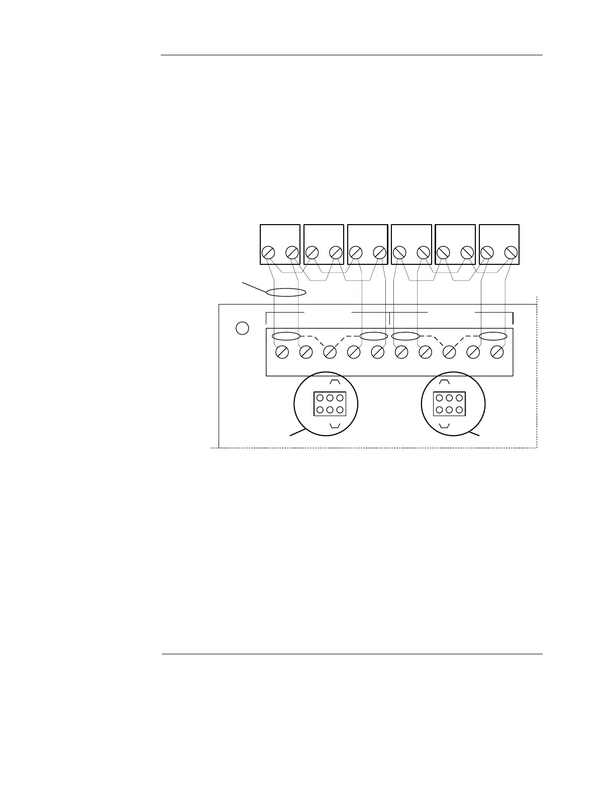
Class A wiring To connect the MSS with an IDNet+ channel to devices using Class A wiring, read the
following instructions and refer to Figure 6-4:
1. Route wiring from the IDNet Circuit Primary Terminals (B+, B-), and SHIELD terminals on
TB1 of the IDNet+ module to the appropriate inputs on the first IDNet device.
Note: Shielded wiring is optional. SHIELD terminations are connected to earth.
2. Route wiring from the first IDNet device to the next as in/out as shown in Figure 6-4. Repeat
for each device.
3. Route wiring from the last IDNet device to the IDNet Circuit Secondary Terminals (A+, A)
and SHIELD Terminals (if used) on TB1 of the IDNet+ module.
4. Ensure that circuit jumpers are configured for Class A operation.
Figure 6-4. Class A wiring
Note: There are two considerations for addressing Class A wired IDNet devices connected to the IDNet+
module:
1. If no remote isolators or isolator bases are on the loops, device addressing can be assigned without
concern for sequence.
2. If remote isolators or isolator bases are on the loops, the required addressing approach is to
start from the “B” side of the A loop output and assign each successive isolator a higher address
than the isolator it proceeds. Follow this sequencing through to the “B” side of the B loop.
IDNet Circuit A
B+ B- A+ A-SHLD
IDNet Circuit B
B+ B- A+ A-SHLD
P1
135
246
135
246
P2
Position 3-5 and 4-6
Class A Wiring
+++---++ +-- -
IDNet Devices
18 to 12 AWG
(0.82 to 3.31 mm
2
)
MSS with IDNet
TB1
Notes:
Set jumpers to Positions 3-5 and 4-6 to
select Style 6 (Class A) operation. (Refer
to P1 and P2 in Figure for correct
orientation)
For this application, the Shield (if present)
can be terminated at both ends for
improved EMI susceptibility.
Circuit A jumpers Circuit B jumpers