5-2
Mounting the panel
Installing the back
box
Store the system electronics containers in a safe, clean, and dry location until the back box
installation is completed and you are ready to install additional modules. Make certain that you
have the necessary hardware before you begin the installation procedure.
Install the back box as shown in Figure 5-1. Use the holes in the back box to secure it to the
wall.
Note: • Conductor entrance and routing restrictions apply to power-limited systems only.
• While the pre-installed system components may be left in the backbox during installation, due to
the danger of metal fragments falling into electronics, it is recommended to remove the dead front
and any bay pans in the system.
• For surface or flush mounting to a wooden wall structure, the back box must be attached with four
3/8-inch-diameter x 1-½-inch-long (9.5 mm x 38 mm) fasteners and four 3/8-inch-diameter (9.5
mm) washers.
• For surface mounting, secure the box to the wall using the tear-drop mounting holes on the back
surface. For flush and semi-flush mounting, secure the box to the wall studs using the indicated
areas (dents in the metal) on the sides of the box. Note that the front surface of the back box must
protrude at least three inches from the wall surface for semi-flush installations.
• Power-limited systems have entrance and routing restrictions for field wiring. See section
“General Field Wiring Guidelines” on page 5-5 for more details.
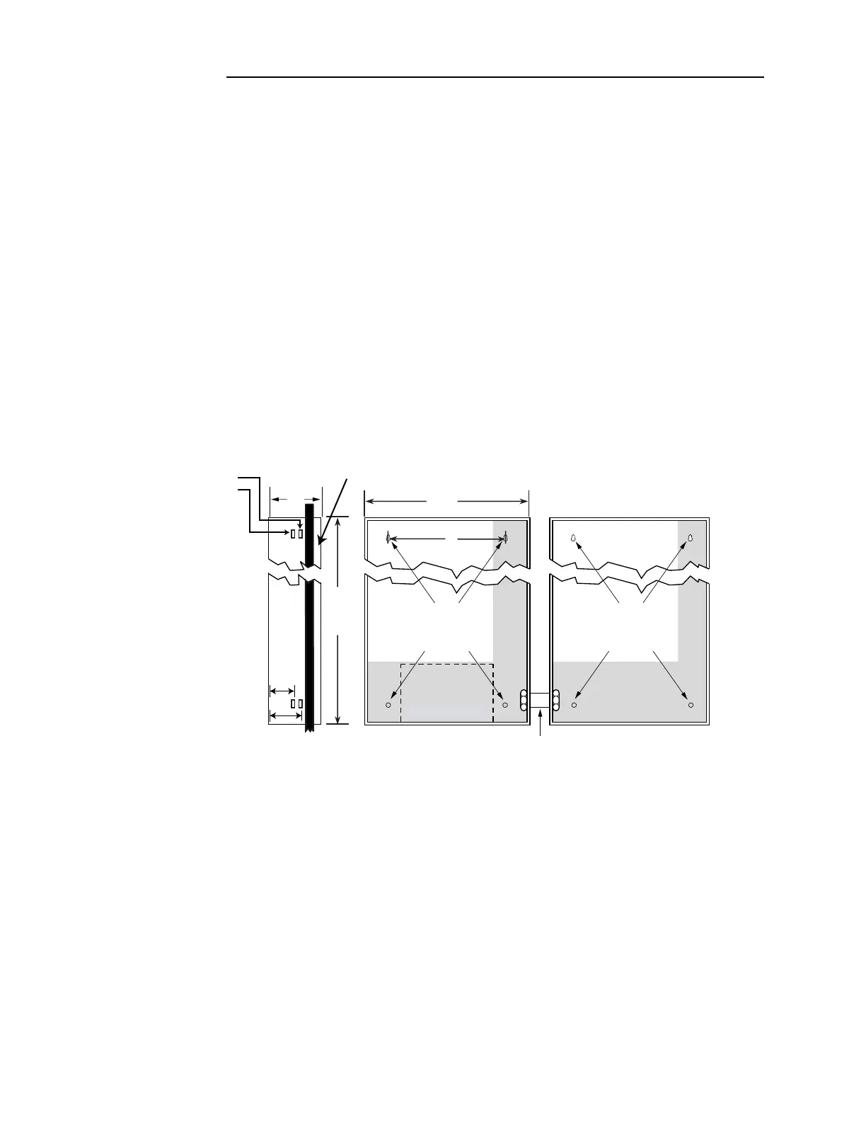
Figure 5-1. Back box installation
Notes:
1. Dimensions shown are typical for all surface and semi-flush installations.
2. Use suitable punch when conduit is required. Knockouts are not provided. Locate and create on-site
as required during installation.
3. A minimum clearance of 5 inches (127 mm) from the hinge side is required to provide a maximum
door opening of 90 degrees.
4. Do not install any power-limited wiring in the shaded area of the back box as shown in Figure 5-1.
This area is reserved for non power-limited devices and circuits. for example, AC power, batteries,
and city circuits. The non power-limited area is determined by the internal barriers, but is always
below and to the right of these barriers.
5. Minimum distance between boxes is 3 1/4 inches (83 mm). Maximum distance between boxes is 10
inches (254 mm).
POTPOT
RESERVED
FOR
BATTERIES
(SEE NOTE 6)
ADDITIONAL
BACK BOX
USE 4 HOLES TO
SECURE BACKBOX
TO THE WALL
USE 4 HOLES TO
SECURE BACKBOX
TO THE WALL
24”
(610 mm)
3 17/32”
(90 mm)
5 17/32”
(140 mm)
16”
(406 mm)
See Notes 3 and 5
6 29/32”
(175 mm)
22”
(559 mm)
(ONE
BAY)
ALIGNMENT MARKERS
FOR WALL STUDS:
6” (152 mm)
4” (102 mm)
WALL
WALL
PANEL
FRONT