EasyManuals Logo

Simplex 4010ES Installation Guide

Simplex 4010ES
110 pages
To Next Page IconTo Next Page
To Previous Page IconTo Previous Page
Page #88 background imageLoading...
Page #88 background image
A-2
Common earth fault ground indicator
Overview This application monitors a system pseudo (A112) that counts the number of ground faults that
occur on the system. Each time this counter increments (i.e., a ground fault occurs), a yellow
LED on the operator interface panel illuminates.
Step 1. Open CPU
card properties
dialog
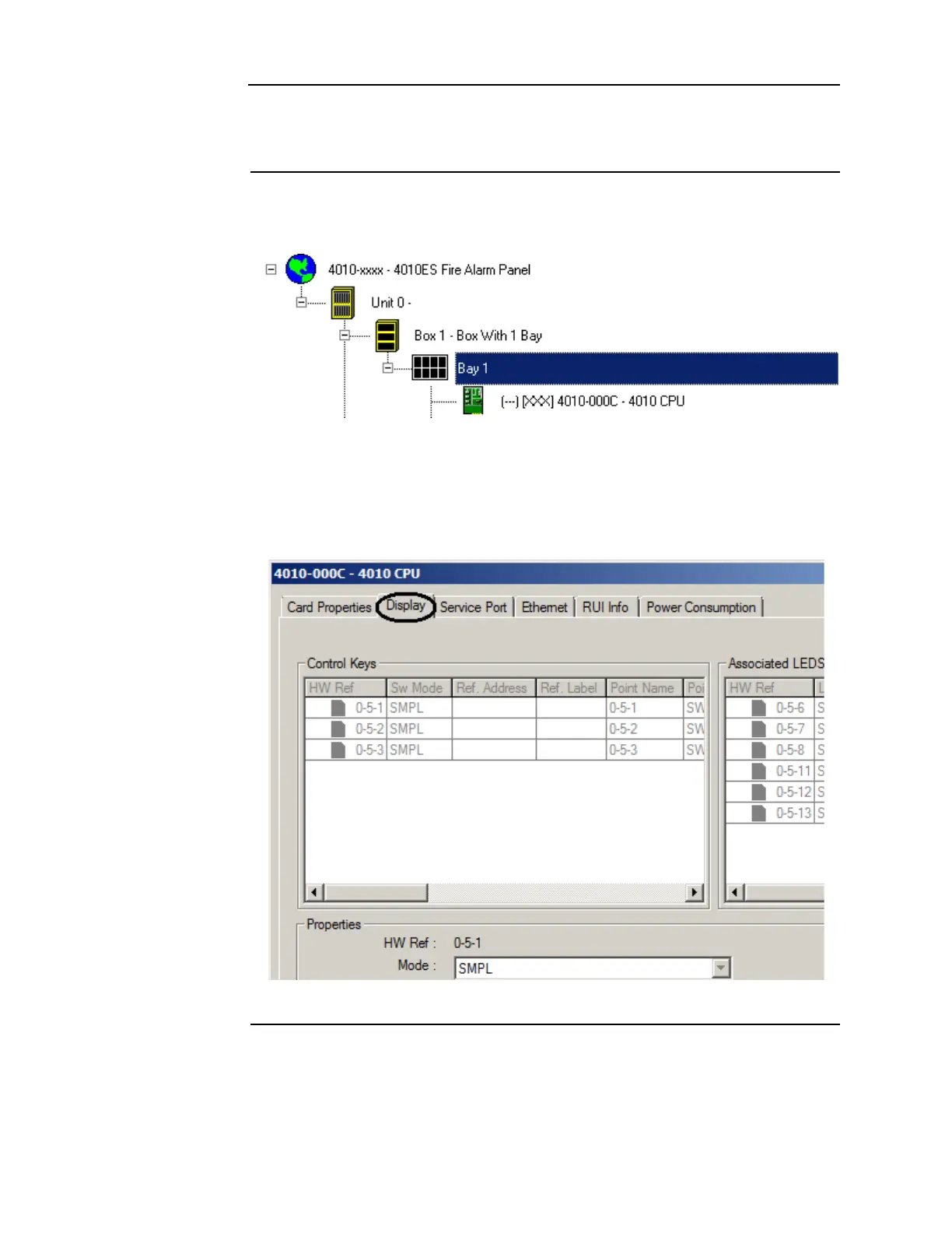
1. Click on the Hardware tab and expand the Unit 0, Box 1, Bay 1 icons to display the CPU
Card. (Click on the + signs to the left of the Unit 0, Box 1, and Bay 1 icons to expand them.)
Figure A-1. Selecting the CPU card
2. Right click on the CPU card icon (it is highlighted in the example above) and select Proper-
ties. When the CPU card properties dialog appears, click on the Display tab as shown in the
example below.
Figure A-2. The Display tab: Display checkbox

Table of Contents

Other manuals for Simplex 4010ES

Questions and Answers:

Question and Answer IconNeed help?

Do you have a question about the Simplex 4010ES and is the answer not in the manual?

Simplex 4010ES Specifications

General IconGeneral
Control Panel TypeAddressable Fire Alarm Control Panel
DisplayLCD
Operating Temperature32°F to 120°F (0°C to 49°C)
Power Supply120V AC or 240V AC
Zones10
Communication PortsRS-232, Ethernet
Signaling Line Circuits (SLCs)2
Notification Appliance Circuits (NACs)4
Max Notification AppliancesVaries based on NAC configuration and power supply
Communication OptionsCellular, Ethernet
Weight30 lbs
Humidity RangeUp to 93% non-condensing
CertificationsUL, FM, CSFM, MEA
Network CapabilityYes

Related product manuals