EasyManuals Logo

Simplex 4010ES Installation Guide

Simplex 4010ES
110 pages
To Next Page IconTo Next Page
To Previous Page IconTo Previous Page
Page #55 background imageLoading...
Page #55 background image
5-11
RUI wiring
Overview The CPU card’s RUI channel supports the following devices:
4009T
4009 TPS
4602 Series RCU/SCU
4606-9102 Remote LCD Annunciator
4100-7400 Series Graphic Annunciators
4100-9400 Series Remote InfoAlarm Command Center
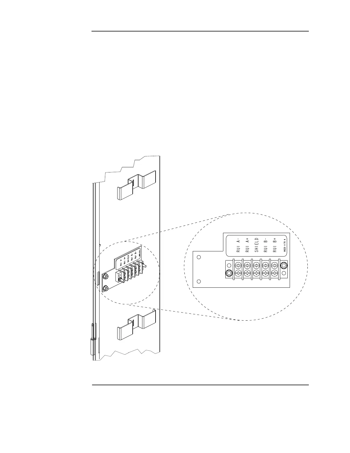
Wire from the CPU card’s RUI interface to the RUI terminal block (Figure 5-11). From there,
wire to each RUI device. The wiring may be Class A or Class B:
Class A wiring allows devices to communicate with the FACP even in the event of a single
open circuit somewhere in the loop. Class A wiring requires that two wires are routed from the
CPU card to each device, and then back again to the CPU card.
Class B wiring allows “T” tapping, and therefore requires less wiring distance per installation
than Class A.
Figure 5-11. Location of the RUI terminal block
Continued on next page

Table of Contents

Other manuals for Simplex 4010ES

Questions and Answers:

Question and Answer IconNeed help?

Do you have a question about the Simplex 4010ES and is the answer not in the manual?

Simplex 4010ES Specifications

General IconGeneral
Control Panel TypeAddressable Fire Alarm Control Panel
DisplayLCD
Operating Temperature32°F to 120°F (0°C to 49°C)
Power Supply120V AC or 240V AC
Zones10
Communication PortsRS-232, Ethernet
Signaling Line Circuits (SLCs)2
Notification Appliance Circuits (NACs)4
Max Notification AppliancesVaries based on NAC configuration and power supply
Communication OptionsCellular, Ethernet
Weight30 lbs
Humidity RangeUp to 93% non-condensing
CertificationsUL, FM, CSFM, MEA
Network CapabilityYes

Related product manuals