EasyManuals Logo

Simplex 4010ES Installation Guide

Simplex 4010ES
110 pages
To Next Page IconTo Next Page
To Previous Page IconTo Previous Page
Page #56 background imageLoading...
Page #56 background image
5-12
RUI wiring, continued
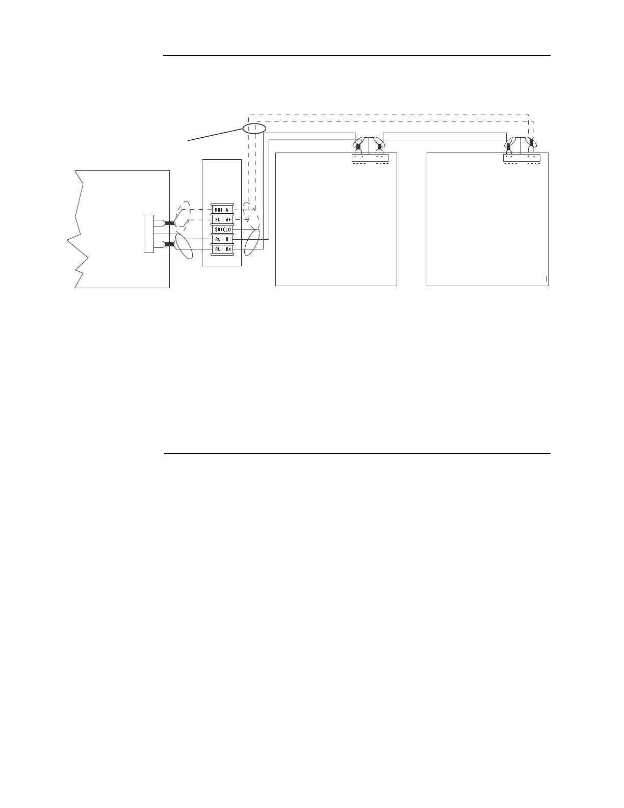
Overview Figure 5-12 depicts Class A and Class B wiring.
Figure 5-12. RUI wiring to the host panel
For more detailed field wiring information on each device, refer to its specific installation
instructions manual. See Chapter 4, “Orderable panels and devices,” for a list of instruction
manuals.
RUI
SHLD
RUI
SHLD
DASHED LINES ARE FOR
CLASS A OPERATION
1. Wire size must be
between 18 AWG (0.8231 mm
2
)
and 12 AWG (3.309 mm
2
).
2. Maximum wiring distance: 2,500 feet
(762 m) to device from CPU card.
3. Maximum “T” tapping length:
10,000 feet (3,048 m).
4. Maintain correct polarity on terminal
connections.
Do not loop wires under terminals.
RUI Device RUI Device
RUI A-
RUI A+
SHIELD
RUI B-
RUI B+
4010ES CPU Card
5. If Class A is not used, leave loop back wires from A+ to B+ and A- to B- on RUI terminal blocks.
6. Shield wire is not required. Twisted wire is recommended for improved noise immunity
Notes:
RUI
Terminal
Block

Table of Contents

Other manuals for Simplex 4010ES

Questions and Answers:

Question and Answer IconNeed help?

Do you have a question about the Simplex 4010ES and is the answer not in the manual?

Simplex 4010ES Specifications

General IconGeneral
Control Panel TypeAddressable Fire Alarm Control Panel
DisplayLCD
Operating Temperature32°F to 120°F (0°C to 49°C)
Power Supply120V AC or 240V AC
Zones10
Communication PortsRS-232, Ethernet
Signaling Line Circuits (SLCs)2
Notification Appliance Circuits (NACs)4
Max Notification AppliancesVaries based on NAC configuration and power supply
Communication OptionsCellular, Ethernet
Weight30 lbs
Humidity RangeUp to 93% non-condensing
CertificationsUL, FM, CSFM, MEA
Network CapabilityYes

Related product manuals