6-7
MSS IDNet wiring
Overview A single IDNet+ channel is provided that can connect up to 248 IDNet devices. The IDNet+
channel has 2 isolated circuits that support either Class A or Class B wiring. Typical devices
include smoke and heat sensors, QuickConnect sensors and a variety of addressable input and/
or output modules. Refer to datasheet S4090-0011 for a list of compatible IDNet devices.
Class A wiring provides an alternate communication path that provides communications to
all devices when a single open circuit fault occurs. Class A wiring requires two wires to be
routed from the IDNet+ Primary Terminals (B+, B-) to each IDNet device, and then back to the
IDNet+ Secondary Terminals (A+, A-).
Note: Wiring is in/out. “T” tapping is not allowed.
Class B wiring allows “T” tapping, and typically results in less wiring used per installation
compared to Class A. IDNet wiring is inherently supervised due to individual device level
communications, and end-of-line resistors are not required.
Wiring
parameters
Table 6-3 identifies the MSS with IDNet wiring parameters that must be considered when
applying this module. For additional wiring information, see the applicable installation
documentation or contact your authorized Simplex Product supplier.
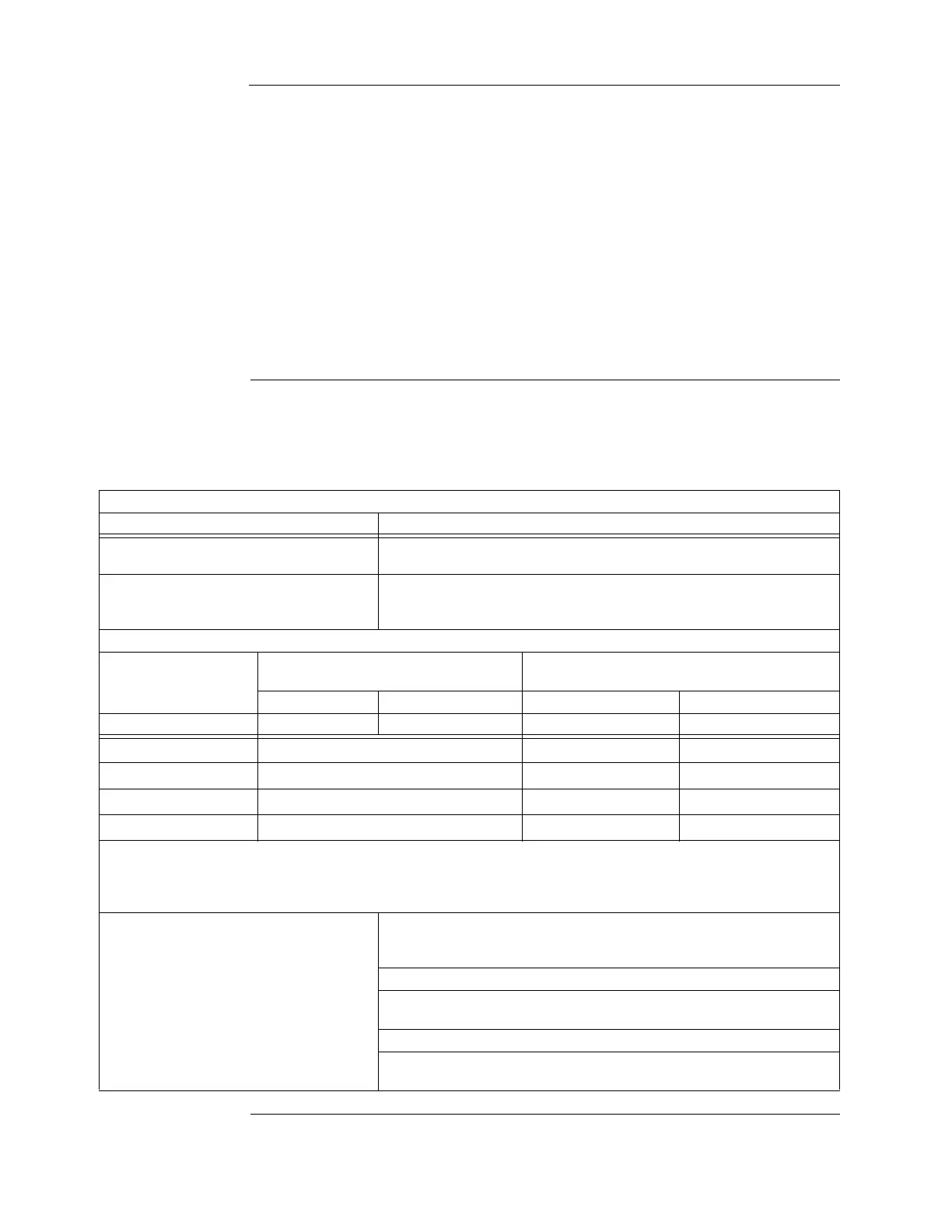
Table 6-3. MSS IDNet wiring parameters
IDNet wiring capacitance parameters
Parameter Value
Maximum supported channel capacitance;
Total of both isolated outputs
The sum of line-to-line capacitance, plus the capacitance of either line-to-
shield (if shield is present) = 0.6 µF (600 nF)
Capacitance between IDNet+ SLCs wiring
(between wires of the same polarity; plus to
plus, minus to minus)
1 µF maximum (this is for multiple IDNet+ channels)
IDNet+ wiring distance limits (see notes below)
Channel loading
Class B wiring, total channel wiring
parameters, including T-Taps
Class A wiring,
total channel wiring parameters
Up to 125 devices 126 to 248 devices Up to 125 devices 126 to 248 devices
Total loop resistance 50 maximum 35 maximum 50 maximum 35 maximum
18 AWG (0.82 mm
2
)
12,500 ft (3.8 km) 4000 ft (1219 m) 2500 ft (76 2m)
16 AWG (1.31 mm
2
)
12,500 ft (3.8 km) 5000 ft (1524 m) 2500 ft (762 m)
14 AWG (2.08 mm
2
)
12,500 ft (3.8 km) 5000 ft (1524 m) 2500 ft (762 m)
12 AWG (3.31 mm
2
)
12,500 ft (3.8k m) 5000 ft (1524 m) 2500 ft (762 m)
Notes: Maximum wiring distance is determined by either reaching the maximum resistance, the maximum capacitance, or the
stated maximum distance, whichever occurs first. Class A maximum distances are to the farthest device on the loop
from either “B” or “A” terminals. For Class B wiring, the maximum distance to the farthest device is limited to the stated
Class A wiring distances.
IDNet+ wiring considerations using 2081-
9044 Overvoltage Protectors
(2081-9044 is UL listed to Standard 60950-1,
Standard for Safety of Information Technology
Equipment)
Note: External wiring must be shielded for lightning suppression, and 2081-
9044 Overvoltage Protectors must be installed at building exit and entrance
locations.
Capacitance; each protector adds 0.006µF across the connected line.
Resistance; each protector adds 3 per line of series resistance; both IDNet
lines are protected; 6 per protector will be added to total loop resistance.
Maximum distance of a single protected wiring run is 3270 ft (1 km).
Refer to document number 574-832, 2081-9044 Overvoltage Protector
Installation Instructions, for additional information.