5-5
General field wiring guidelines
Power-limited
guidelines
For wiring guidelines, see the applicable installation documentation or contact your authorized
Simplex Product supplier. Make sure these guidelines are accounted for before wiring for
power-limited systems:
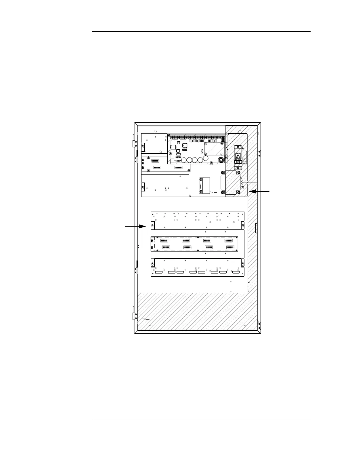
• Non-power limited field wiring (AC power, batteries, city connection) must be installed
and routed in the shaded areas shown in Figure 5-5.
• Power-limited field wiring must be installed and routed in the non-shaded areas shown in
Figure 5-5, with the exception of city wiring.
• Excess slack should be kept to a minimum inside the back box enclosure. The wiring
should be neatly dressed and bundled together using wire ties.
Figure 5-5. Field wiring guidelines
• Tie the wiring located between bays to the internal wiring troughs, if applicable.
• When powering remote units or switching power through relay contacts, power for these
circuits must be provided by a power-limited power supply listed for fire-protective
signaling use. An EOL relay must be used to supervise the auxiliary power circuit.
• Auxiliary power only: Supervision must be provided if the auxiliary power circuit is to be
wired as a power-limited circuit. In order to connect a circuit using power-limited wiring,
the devices being powered must all be addressable, or a UL listed EOL relay must be used
to supervise the circuit. Refer to Figure 5-6 for wiring directions for the EOL relay.
Continued on next page
NON-POWER LIMITED
WIRING AREA
POWER LIMITED
WIRING AREA