EasyManuals Logo

Simplex 4010ES Installation Guide

Simplex 4010ES
110 pages
To Next Page IconTo Next Page
To Previous Page IconTo Previous Page
Page #15 background imageLoading...
Page #15 background image
2-3
CPU, continued
Overview
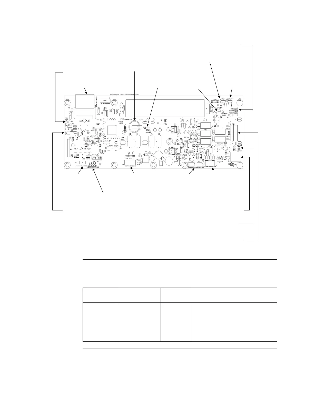
Figure 2-2. Dead front-mounted CPU with a 2 x 40 display (back view)
CPU LEDs The tables below outline the functions of the LEDs on the CPU card.
Continued on next page
RUI TROUBLE LEDs (LED1-LED3)
RUI ENABLE JUMPER (P1)
BATTERY (BT1)
PIEZO CONNECTION (BUZ1)
BATTERY ENABLE LCD CONTRAST RUI SHIELD
COMPACT FLASH (P3) JUMPER (P5) ADJUST (R23) JUMPER (P2)
COLD START KEYPAD MEMBRANE 24V POWER/COMMS
SWITCH (SW3) CONNECTOR (P8) CONNECTORS (P9 & P10)
BOOTLOADER STATUS LEDs (LED7-LED10) SERIAL SERVICE PORT (P11)
RESET SWITCH (SW1) ETHERNET SERVICE PORT (J7)
ETHERNET STATUS LED (LED5) & ACTIVITY LED (LED6)
RUI PLUGGABLE TERMINAL BLOCK (TB1)
Table 2-1. Reset LED
Reference
designator
Silkscreen name Color Status
LED4 RESET Yellow
ON = CPU is in reset
FLASHING = Board is unable to come
out of reset. Possibly corrupt CFIG, or
board needs to be replaced.
OFF = CPU is running normally

Table of Contents

Other manuals for Simplex 4010ES

Questions and Answers:

Question and Answer IconNeed help?

Do you have a question about the Simplex 4010ES and is the answer not in the manual?

Simplex 4010ES Specifications

General IconGeneral
Control Panel TypeAddressable Fire Alarm Control Panel
DisplayLCD
Operating Temperature32°F to 120°F (0°C to 49°C)
Power Supply120V AC or 240V AC
Zones10
Communication PortsRS-232, Ethernet
Signaling Line Circuits (SLCs)2
Notification Appliance Circuits (NACs)4
Max Notification AppliancesVaries based on NAC configuration and power supply
Communication OptionsCellular, Ethernet
Weight30 lbs
Humidity RangeUp to 93% non-condensing
CertificationsUL, FM, CSFM, MEA
Network CapabilityYes

Related product manuals