2-4
CPU, continued
CPU LEDs
Continued on next page
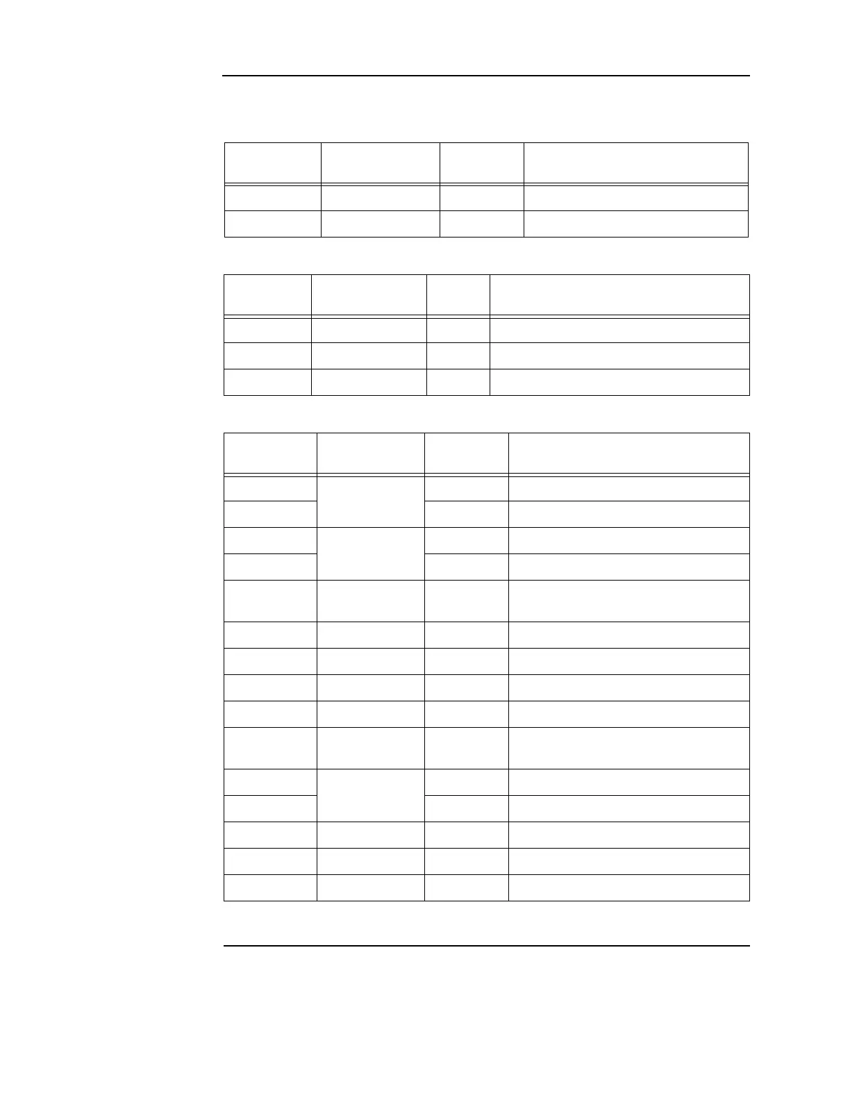
Table 2-2. Ethernet LEDs
Reference
designator
Silkscreen name Color Status
LED5 STATUS Green ON = Cable connected
LED6 ACTIVITY Red FLASHING = Ethernet activity
Table 2-3. RUI trouble LEDs
Reference
designator
Silkscreen name Color Status
LED1 OPEN Yellow ON = Class A fault (open-circuit) or a short
LED2 B SHORT Yellow ON = Short-circuit on the primary side
LED3 A SHORT Yellow ON = Short-circuit on the secondary side
Table 2-4. Front panel LEDs
Reference
designator
Silkscreen name Color Status
LED11
USER-DEF A
Red ON = User-definable key A active (Note)
LED12 Yellow ON = User-definable key A active (Note)
LED13
USER-DEF B
Yellow ON = User-definable key B active (Note)
LED14 Red ON = User-definable key B active (Note)
LED15
ALARM
SILENCED
Yellow ON = Alarm silenced
LED16 TRBL Yellow ON = Trouble
LED17 SUPV Yellow ON = Supervisory
LED18 PRI2 Red ON = Priority 2 alarm
LED19 FIRE Red ON = Alarm
LED20 AC POWER Green
ON = System power is functioning
properly
LED21
USER-DEF C
Yellow ON = User-definable key C active (Note)
LED22 Green ON = User-definable key C active (Note)
LED23 CTRL 1 Yellow ON = Control key 1 active
LED24 CTRL 2 Yellow ON = Control key 2 active
LED25 CTRL 3 Yellow ON = Control key 3 active
Note: Only one LED in each user-definable pair will be on at a time, never both.