EasyManuals Logo

Simplex 4010ES Installation Guide

Simplex 4010ES
110 pages
To Next Page IconTo Next Page
To Previous Page IconTo Previous Page
Page #76 background imageLoading...
Page #76 background image
7-4
Ethernet service port
Ethernet service
port overview
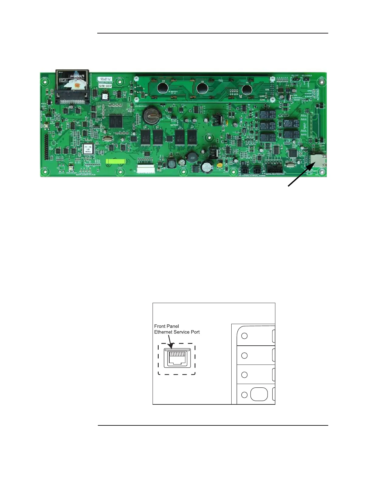
The Ethernet service port J7 on the CPU card is used to connect the panel to a local PC. See
Figure 7-4 for the port location.
Figure 7-4. Ethernet service port
The Ethernet service port connects to the front panel Ethernet connection through a standard
straight (non-crossover) Ethernet patch cable. The front panel Ethernet connection is located
on the top left of the 4010ES front panel. The service technician should connect his PC to the
CPU card through this front panel connection with a standard straight Ethernet cable. If this
connection is not available, you may plug the CPU Card connector J7 directly to the PC with a
standard straight Ethernet cable.
Note: If a BNIC card is used with the system, the CPU card Ethernet connection connects to it. The BNIC
card then connects to the Front Panel Ethernet Connection board
.
Figure 7-5. Front Panel Ethernet Service Port
Ethernet SERVICE PORT (J7)
RJ45 TYPE

Table of Contents

Other manuals for Simplex 4010ES

Questions and Answers:

Question and Answer IconNeed help?

Do you have a question about the Simplex 4010ES and is the answer not in the manual?

Simplex 4010ES Specifications

General IconGeneral
Control Panel TypeAddressable Fire Alarm Control Panel
DisplayLCD
Operating Temperature32°F to 120°F (0°C to 49°C)
Power Supply120V AC or 240V AC
Zones10
Communication PortsRS-232, Ethernet
Signaling Line Circuits (SLCs)2
Notification Appliance Circuits (NACs)4
Max Notification AppliancesVaries based on NAC configuration and power supply
Communication OptionsCellular, Ethernet
Weight30 lbs
Humidity RangeUp to 93% non-condensing
CertificationsUL, FM, CSFM, MEA
Network CapabilityYes

Related product manuals