5-7
Connecting 4010ES basic components
Connecting the
CPU and the
operator interface
Note: All the basic components come pre-installed with the system. The connections are shown for
reference purposes.
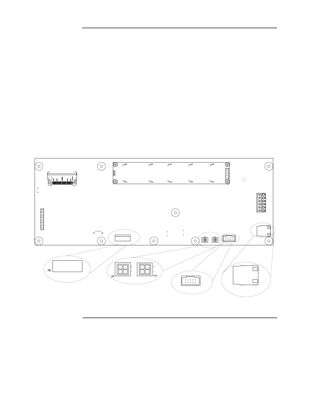
To connect the CPU and the operator interface, follow the steps below:
1. Place the white spacer on the dead front.
2. Attach the CPU card and the piezo to the dead front, using metal screws provided.
3. Attach the Keypad Membrane cable of the operator interface to port P8 on the CPU card
(Figure 5-7). To do so:
a. Slide down the keypad connector shroud on the CPU card.
b. Insert the Keypad Membrane cable into the connector. Do not twist the flat cable.
c. Slide the shroud back up into the connector while holding the flat cable in place.
4. Attach the Ethernet connection board using the 734-232 RJ45 cable.
5. Attach the perle box using the 734-229 cable.
6. Connect port P9 or P10 of the CPU card to the dead front connection (P1) port on the top-
bay power distribution interface (PDI) card (Figure 5-7 and Figure 5-8). Use the
734-008 4-pin connector harness provided.
Figure 5-7. CPU card rear view
Continued on next page
SERIAL SERVICE PORT (P11)
ETHERNET SERVICE PORT (J7)
KEYPAD MEMBRANE