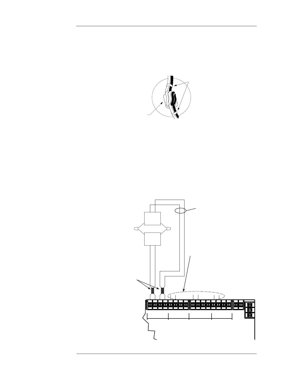
6-5
MSS NAC wiring
Class A NAC
Wiring
To connect the MSS to reverse-polarity, non-addressable notification appliances using Class A
wiring, read the instructions below and refer to Figure 6-2.
1. When connecting the NAC wires to the terminal block, they need to pass through a ferrite
bead to reduce radiated emissions. Route the wires to the supplied ferrite bead. Loop the
wires twice through the bead and secure with two cable ties as shown in Figure 6-1. The
cable ties are supplied in the panel’s ship group.
Figure 6-1. NAC ferrite bead wiring
2. Route wire (between 12 AWG [3.309 mm
2
] and 18 AWG [0.8231 mm
2
]) from the “B+”,
“B-”, and SHIELD (if used) outputs on TB2 of the MSS to the appropriate inputs on a
peripheral notification appliance. Use NAC1, NAC2, NAC3 or NAC4.
3. Route wire from the first appliance to the next one. Repeat for each appliance.
4. Route wire from the last appliance to the A+ and A- inputs on the same NAC circuit of TB1
of the MSS.
5. Repeat steps 1 through 4 for each NAC output you want to use.
6. Leave the 10 KOhms, ½ W, brown/black/orange resistor (378-030) on each unused circuit.
The circuit must connect “B+” to “B-” terminals. No external end-of-line resistor is needed
for circuits in use.
Figure 6-2. Class A NAC wiring
TYPICAL
APPLIANCE
RED
RED
RED
TYPICAL
APPLIANCE
BLK
BLK
BLK
12 AWG (3.309 mm
) to
18 AWG (0.8231 mm
2
)
Important: Conductors must test free of
all grounds.
Leave the 378-030 EOL
Resistor (10 KOhms, ½ W;
brown/black/orange) on
unused
circuits
Ferrite beads
required for RF immunity
to CE specified levels.
""!!""!!""!!""!!
!58
0/7%2
.!#.!#.!#.!#