6-12
MSS auxiliary relay wiring
Guidelines The MSS includes one on-board, programmable relay.
• All wiring must be between 18 AWG (0.8231 mm
2
) and 12 AWG (3.309 mm
2
).
• When power through auxiliary contacts is provided by the MSS, wiring is power-limited.
• When power through auxiliary contacts is not provided by the MSS, use in-line fuse holder 208-165
with 208-183, 1A fuse with attached cap (supplied separately). If the power source is not power-limited
to the requirements of UL864, wiring is to be segregated to the non-power-limited spaces of the
cabinet.
• The relay circuit is not supervised.
• The relay circuit is rated to switch 2 A at 30 VAC or 30 VDC, resistive load.
• Relay contacts are Form C dry contacts. Suppression is provided to earth. Do not switch voltages
greater than rating, or damage may result.
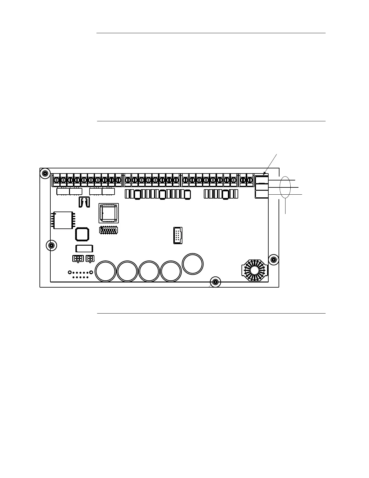
Wiring Figure 6-7 shows MSS auxiliary relay wiring.
Figure 6-7. Auxiliary relay wiring
)$.ET#IRCUIT
""3(,$!!""3(,$!!
)$.ET#IRCUIT
""!!""!!""!!""!!
!58
0/7%2
.!#.!#.!#.!#
MSS
12 AWG (3.309 mm
2
) to
18 AWG (0.8231 mm
2
)
Dedicated auxiliary
relay terminal block
.##./
!58
4"
NORMALLY
OPEN
COMMON
NORMALLY
CLOSED