EasyManuals Logo

Simplex 4010ES Installation Guide

Simplex 4010ES
110 pages
To Next Page IconTo Next Page
To Previous Page IconTo Previous Page
Page #47 background imageLoading...
Page #47 background image
5-3
Mounting the panel, continued
Attaching the
dead front
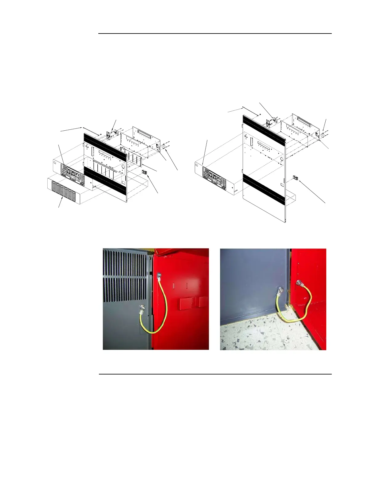
To attach the 4010ES panel dead fronts containing the operator interface and the 48-LED
Module (where applicable), perform the following steps:
1. Align the dead front hinges with the hinge pins on the back box, and slide the door down
onto the hinge pins.
2. Attach the two grounding straps to the back box with the # 6 hex flange nuts. See Figure 5-3.
The grounding straps should already be attached to the dead front.
Figure 5-2. 4010ES dead fronts
Figure 5-3. Dead front grounding straps
,%$
-ODULE
'ROUNDING3TRAP
/PERATOR)NTERFACE
#05
#ARD
$EAD&RONT,ATCH
0IEZO
,%$-ODULE/VERLAY
%THERNET3ERVICE0ORT
$EAD&RONT,ATCH
#05
#ARD
0IEZO
%THERNET3ERVICE0ORT
'ROUNDING3TRAP
/PERATOR)NTERFACE
One-Bay
Two-Bay
Top
Bottom

Table of Contents

Other manuals for Simplex 4010ES

Questions and Answers:

Question and Answer IconNeed help?

Do you have a question about the Simplex 4010ES and is the answer not in the manual?

Simplex 4010ES Specifications

General IconGeneral
Control Panel TypeAddressable Fire Alarm Control Panel
DisplayLCD
Operating Temperature32°F to 120°F (0°C to 49°C)
Power Supply120V AC or 240V AC
Zones10
Communication PortsRS-232, Ethernet
Signaling Line Circuits (SLCs)2
Notification Appliance Circuits (NACs)4
Max Notification AppliancesVaries based on NAC configuration and power supply
Communication OptionsCellular, Ethernet
Weight30 lbs
Humidity RangeUp to 93% non-condensing
CertificationsUL, FM, CSFM, MEA
Network CapabilityYes

Related product manuals