6-11
MSS auxiliary power wiring, continued
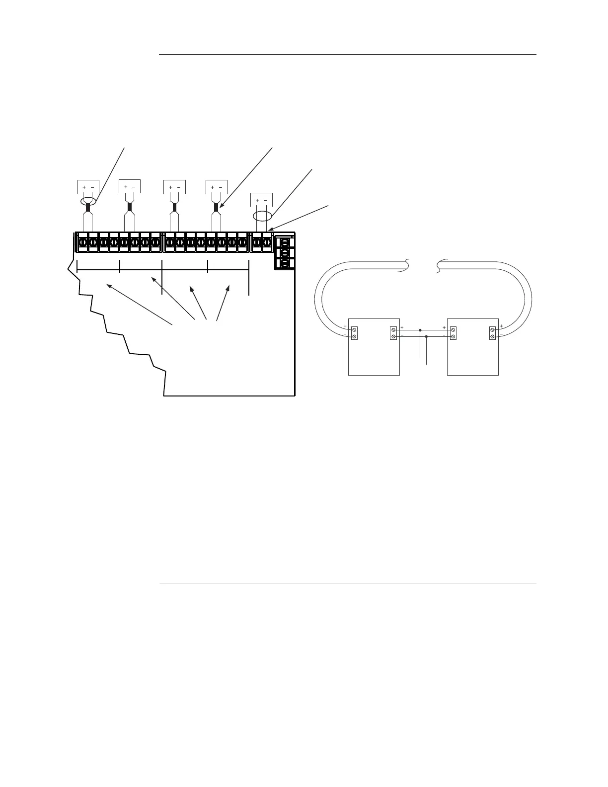
Wiring The MSS can connect to auxiliary power appliances via the dedicated auxiliary power tap. If
more power is needed, any of the three NAC outputs can be used for auxiliary power.
Figure 6-6. Auxiliary power wiring
AUXILIARY
POWER
AUXILIARY
POWER
AUXILIARY
POWER
AUXILIARY
POWER
• Maximum allowed NAC current consumption (aux power plus NACs): 8 A
(Special Application) or 4 A regulated 24 VDC.
Maximum per NAC: 3 A
• Maximum allowed auxiliary power current consumption: 4 A (total supply).
Maximum per auxiliary output: 2 A
• Class A wiring is possible only if a 4090-9117 Power Isolator is used.
• International systems require ferrite beads. Use kit 4100-5129.
Devices
Primary Return
TB1 TB2
24V
0V
TB1 TB2
To MSS
Class A aux power wiring requires the use
of 4090-9117 IDNet Power Isolators, as
shown above.
4090-9117
ISOLATOR
4090-91
17
ISOLA
TOR
Dedicated auxiliary
power screw terminal
(configured in the
Programmer)
NAC points must be
reconfigured as
auxiliary power
output points in the
programmer
12 AWG (3.309 mm
2
) to
18 AWG (0.8231 mm
2
)
12 AWG (3.309 mm
) to
18 AWG (0.8231 mm
2
)
Ferrite bead
Required for RF
immunity to CE
specified levels.
Use kit 4100-5129.
""!!""!!""!!""!!
!58
0/7%2
.!#.!#.!#.!#
66
4"
4"
4"
AUXILIARY
POWER
MSS