EasyManuals Logo

Simplex 4010ES Installation Guide

Simplex 4010ES
110 pages
To Next Page IconTo Next Page
To Previous Page IconTo Previous Page
Page #26 background imageLoading...
Page #26 background image
2-14
48-LED Module
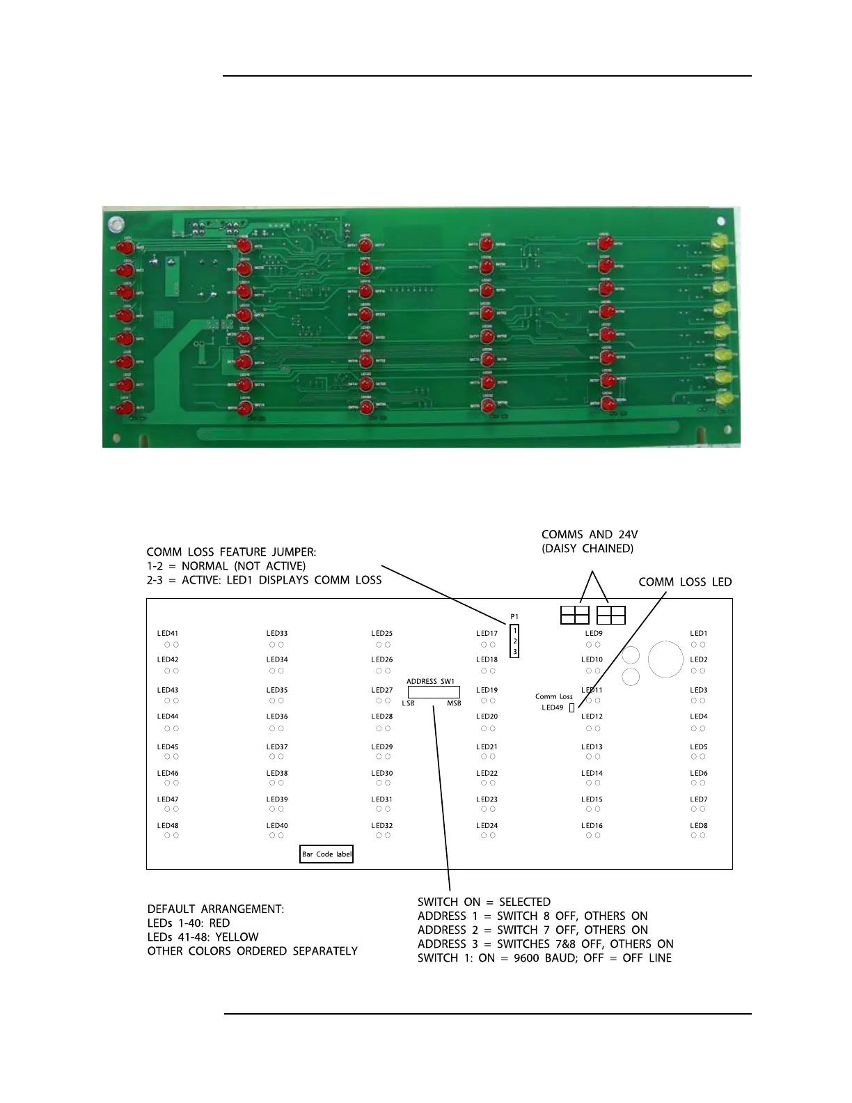
Overview The 48-LED Module (Figure 2-7) comes pre-installed inside some base configurations of the
4010ES panel. Each LED can be associated with a point, or group of points. By default, the
module is supplied with red LEDs, except for the last column which has yellow LEDs. All of
the LEDs can be replaced by different color LEDs. Refer to Chapter 4, “LED Kits for the 48-
LED Module,” for a list of LED kits. Refer to Chapter 5, “Installing 4010ES Systems,” for
instructions on replacing LEDs.
Figure 2-7. 48-LED Module (front view)
Figure 2-8 outlines what the different LEDs, jumpers and switches represent.
Figure 2-8. 48-LED Module LEDs, jumpers and switches (rear view)

Table of Contents

Other manuals for Simplex 4010ES

Questions and Answers:

Question and Answer IconNeed help?

Do you have a question about the Simplex 4010ES and is the answer not in the manual?

Simplex 4010ES Specifications

General IconGeneral
Control Panel TypeAddressable Fire Alarm Control Panel
DisplayLCD
Operating Temperature32°F to 120°F (0°C to 49°C)
Power Supply120V AC or 240V AC
Zones10
Communication PortsRS-232, Ethernet
Signaling Line Circuits (SLCs)2
Notification Appliance Circuits (NACs)4
Max Notification AppliancesVaries based on NAC configuration and power supply
Communication OptionsCellular, Ethernet
Weight30 lbs
Humidity RangeUp to 93% non-condensing
CertificationsUL, FM, CSFM, MEA
Network CapabilityYes

Related product manuals