CA4
2/50
/52 Radar operation Chapter 8
105
8.2.2 Initial radar display setup
After the installation has been completed there are a number of para-
meters to check out and adjust according to the actual circumstances.
All defaults from the factory are tested for various situations, however,
if your situation is such that adjustments are required, please refer to
the details described in this section.
) The Scanner type is preset to Auto detect and as such, the system
will automatically initiate the correct parameters for the connected
scanner.
MENU
Call up the menu bar, and…
6,3
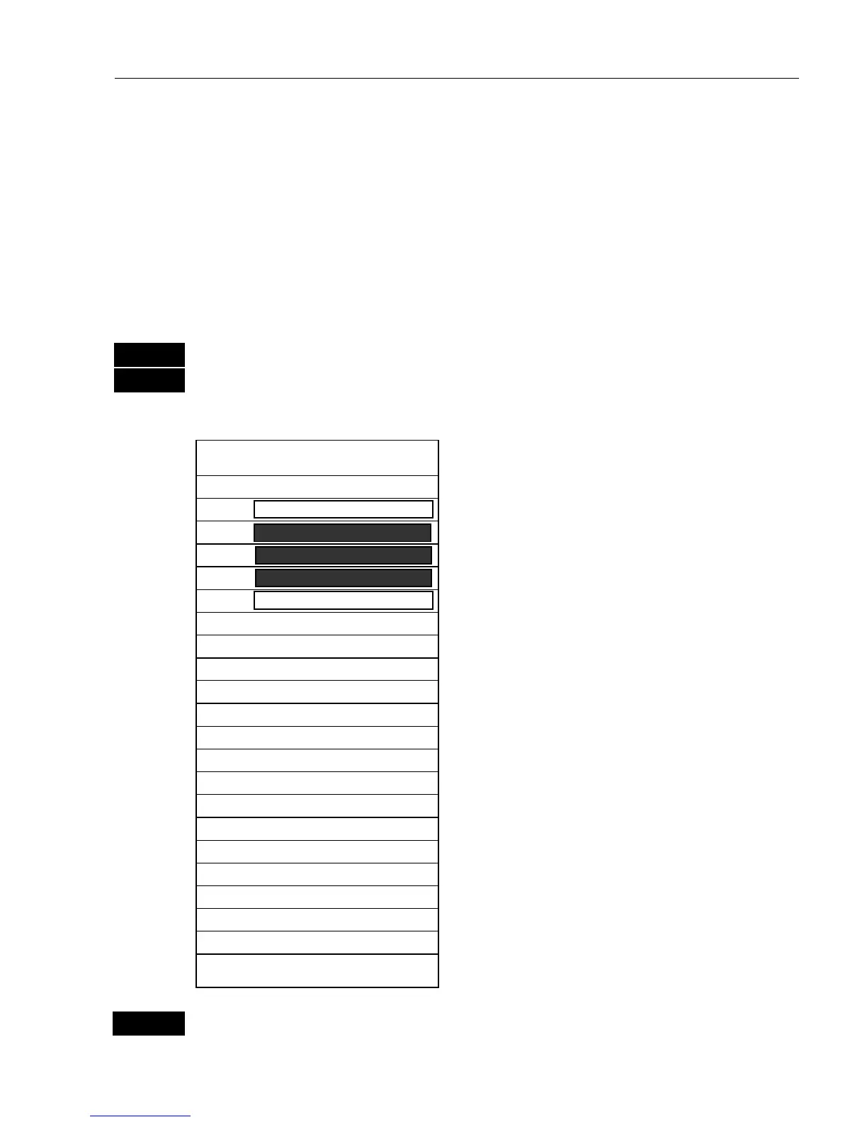
load Radar setup display
Example:
HU
0.50nm
Power off
TI
Tune
AUTO
Gain
AUTO
Sea
AUTO
Rain
Scanner type Auto detect
Antenna height 05m
Heading adjust 000.0°
Tuning reference 079
Zero range/timing 0109
Sensitivity 048
GZ target threshold 5
Stand-by time 000000h
Transmit time 000000h
Auto sea minimum 035
Auto sea default 050
Auto sea maximum 070
Auto gain minimum 080
Auto gain default 090
Auto gain maximum 105
Test scanner Activate
Head-Up, North-Up, True Motion.
Range scale is 0.50nm.
Power off, X-MIT, Stand-by.
TI: Tuning indicator.
*Tune, Gain, Sea: Press
CLR
to toggle
between auto and manual operation.
*Rain: Rain Clutter / FTC.
Scanner type: Auto detect,
Demo, (and
RB714A, RB715A, RB716A)
Antenna height: 5m above water.
*Heading adjust: in degrees to 0°.
*Tuning reference: adjust if necessary.
*Zero range/timing: adjust if necessary.
*Sensitivity: adjust if necessary.
*GZ Target Threshold: levels of 1 to 7.
Stand-by time: Elapsed standby time.
Tx time: Elapsed transmission time.
*Auto sea and Auto gain are preset for
best performance under normal
conditions.
*= Only adjustable in X-MIT mode.
More details on next pages.
Test scanner (for technicians only).
ADJ
Open for adjustment
- a warning will pop up that you are about to change settings for the