Simrad SP70
28
850--164186 A
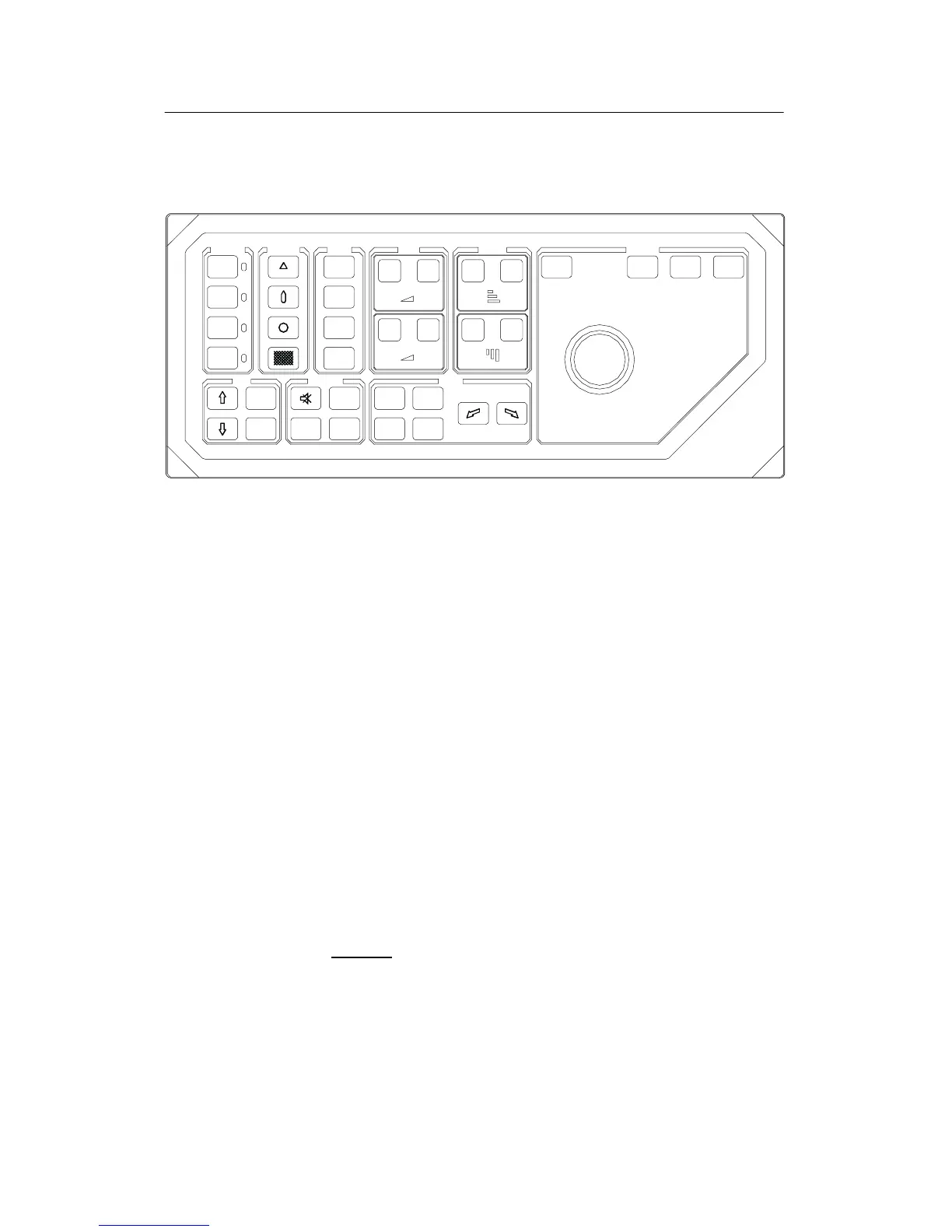
3.3 The Sonar Operating Panel
Figure 20 - Sonar Operating Panel
POWER
Up
Middle
Down
MAIN SW.
SYMBOL
Gain
H -
Range
H -
Gain
V -
Range
V -
Gain
H +
Range
H +
Gain
V +
Range
V +
MODE
Mode
1
GAIN
Mode
2
Mode
3
Mode
4
RANGE CURSOR
SelectMenu
View
Object
SONAR OPERATING PANEL
TILT
Manual
Auto
VARIOUS
Zoom
Record
Off
Centre
Position
Track
Manual
Target
Track
Auto
Search
TRAIN
(CD5377B)
SIMRAD
System input is provided by an ergonomiclly designed control
panel. Sonar functions may be accessed and activated using the
menu field and console mounted roller ball. Frequently used
functions are directly available through designated control panel
buttons which are grouped according to purpose.
A thorough understanding of system functions and controls is
necessary to optimize overall performance. Sonar conditions
vary, sometimes drastically, and it is not possible to identify
settings that will provide the best data at all times. Careful study
of this section and that concerning Modes of operation is highly
recommended, preferably while exploring the sonar’s various
functions at the same time. System operation is a dynamic activity
requiring regular adjustments and fine tuning to achieve the best
possible results under varying environmental conditions.
Main switch
Main switch functions control power to the sonar, hoisting and
lowering of the transducer and indicates the transducer’s current
position.
POWER
Pressing POWER for approximately two seconds powers up the
sonar. The adjacent green LED blinks while the Sonar control unit
is booting and remains illuminated once the system is operational.
Before the sonar can be powered down, the transducer must be in
the UP position. Pressing the POWER button for approximately
two seconds secures power to the unit which is confirmed by the
adjacent green LED being extinguished.