133
SJ6826RT, SJ6832RT
213560ABA
General Section 5 – Procedures
5.2-4 Wheel Bolt / Nut Inspection and
Torquing Procedure
It is necessary to check the torque on all wheel
nuts and wheel bolts at pre-delivery, after 8 hours of
operation and at weekly intervals using the following
procedure:
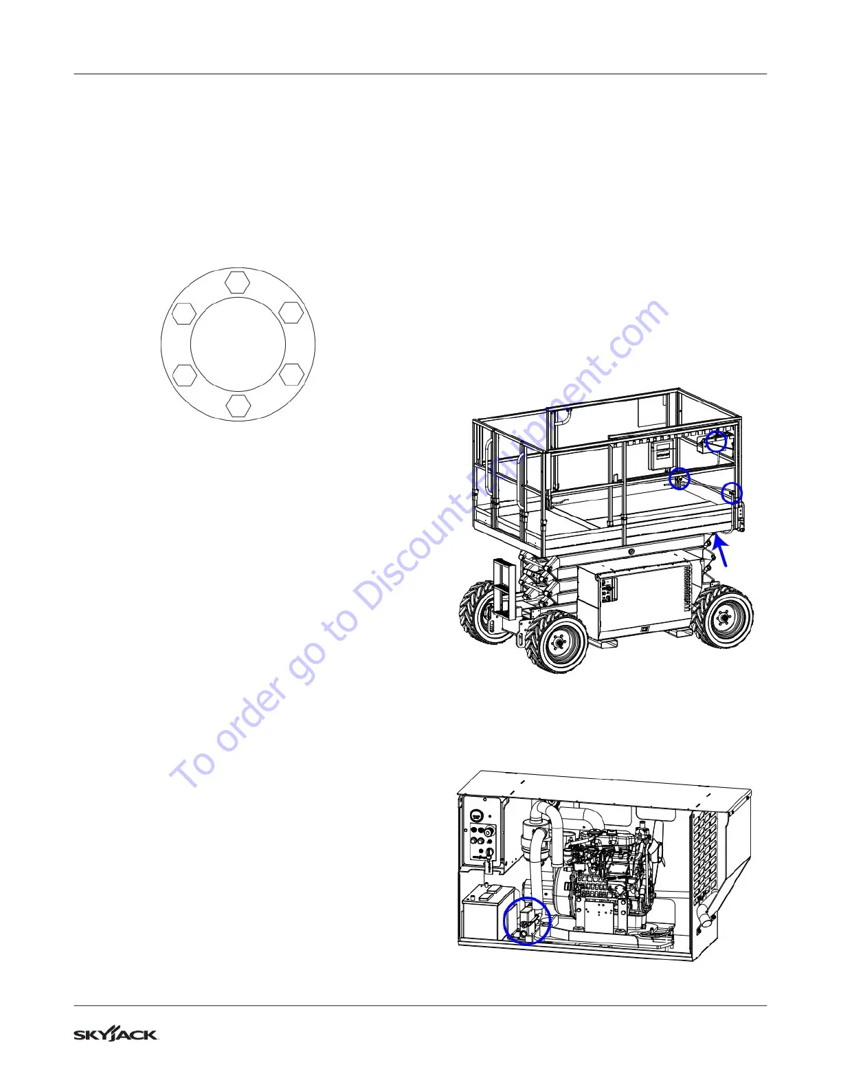
1. Conrm that each wheel fastener is torqued to
90 ±5 ft•lb. All fasteners must be torqued using
the tightening sequence below.
1
6
4
2
5
3
2. Re-torque as necessary until all fasteners are
properly torqued.
5.2-5 Wheel Reinstallation and Torquing
Procedure
When a Wheel/Tire Assembly has been removed or
replaced, it will be necessary to follow the procedure
below to ensure proper installation:
1. Inspect wheel fastener threads for damage and
defects. Replace if defective.
2. Clean the mounting surfaces of hub and the
wheel rim of debris, rust, excess paint, etc.
3. Mount wheel on the hub, centering mounting
holes on the wheel studs or bolt holes. Use
appropriate lifting device as required.
4. Install wheel nuts or wheel bolts and hand
tighten to center the rim.
5. Tighten nuts or bolts to approximately
50 ft•lb torque using the tightening sequence
shown above.
6. Tighten to 90 ft•lb using the same sequence.
7. Repeat the torque sequence to conrm that
none have changed from 90 ft•lb. If any are
found below 90 ft•lb, repeat complete sequence
until there is no change in torque values. If
possible, drive the machine prior to checking
torques.
8. Check torque values after 8 hours of operation
and then at weekly intervals.
5.2-6 Reconnecting the Platform Control
Box for Use from the Ground
1. To facilitate servicing the aerial platform, the
platform control box may be removed from the
platform, and reconnected inside the hydraulic
cabinet, to allow functions to be accessed from
the ground.
2. From the platform, remove the quick release
pins securing the platform control box to the
control box mount and cable guides.
3. Disconnect the control box cable from the
scissor control cable (swing down the small
latch on the side of the connector and pull the
connectors apart). The connectors are located
near the front right corner of the platform on the
underside.
4. Bring the control box down from the platform to
the ground.
5. Locate the control cable connectors inside the
engine cabinet.
To order go to Discount-Equipment.com