166
SJ6826RT, SJ6832RT
213560ABA
Section 5 – Procedures Load Sensing System
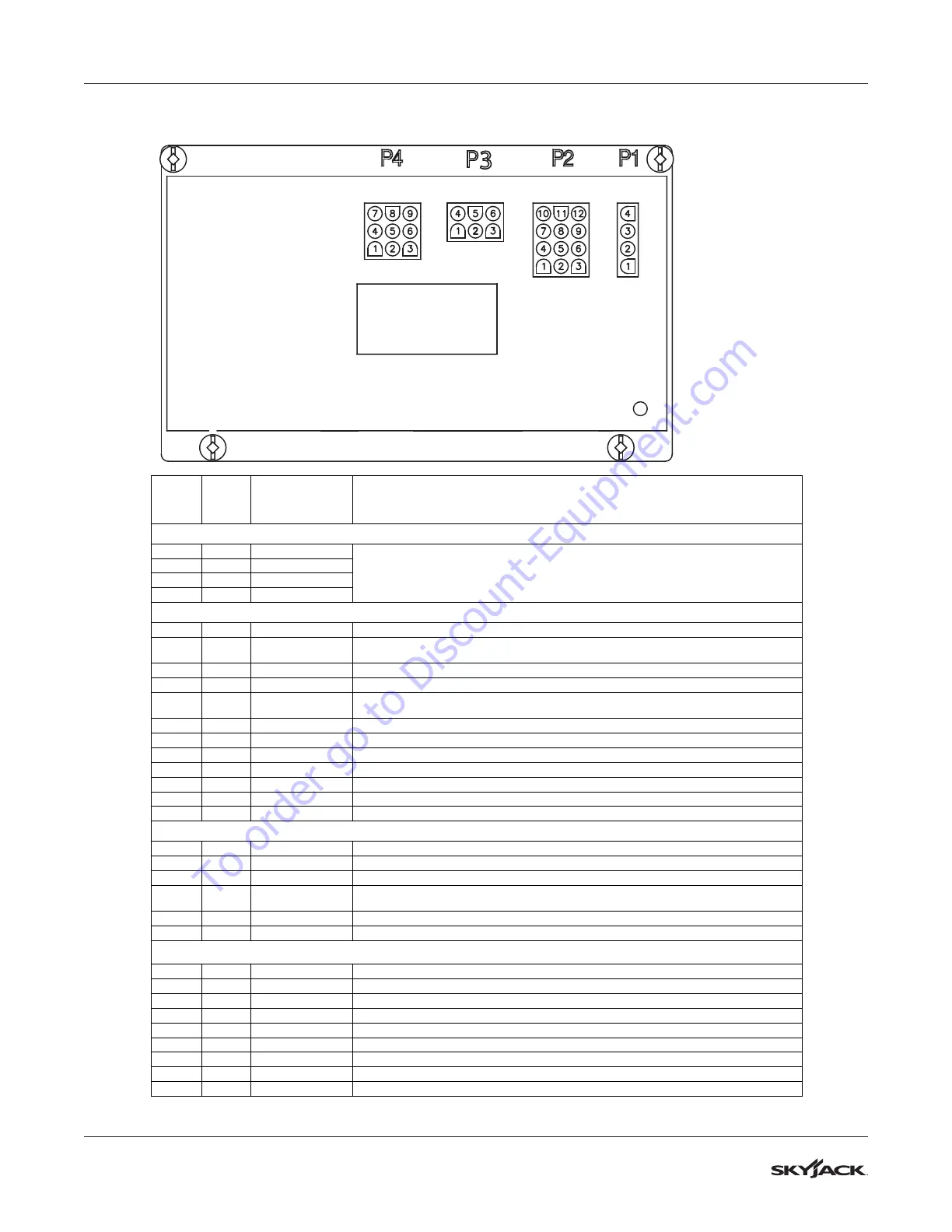
5.5-3 Load Sense Module (CM1) Pin Reference Table (GP-102)
LED
GP102 CONTROL MODULE
PLUG
#
AND
WIRE FUNCTION
Calibration Connection (RS232)
Not connected –used for hand held calibration device connection
Inputs
12V Input from S10 PLTF/Idle/Base Key Switch for Base selected
*required for any movement from Base*
12V Input from S3 Lift/Off/Drive switch for Raise requested
12V Input from S3 Lift/Off/Drive switch for Lower requested
12V Input IF BOTH Emergency Stops are energized
*required for any movement from Platform*
12V Input thru S3 Lift/Off/Drive switch from Joystick Forward drive requested
12V Input thru S3 Lift/Off/Drive switch from Joystick Reverse drive requested
12V Input From LS1 High Speed Limit Switch To Verify ON/OFF Limits
0V GND (-) Negative Reference From Base Terminal Strip
12V Main Power Input thru Main Power Relay 10BCR From Base Terminal Strip
Outputs
12V Output To FL-22 Flashing Light
12V Output To BP-29 Beeper
12V Output To Overload Warning Lights On Base and Platform Emergency Stops
12V Output To 28ACR1 & 28ACR2 Pump Dump Enable Relay’s and 28CR Down
Enable Relay
0V GND (-) Negative Reference for Flashing Light and Beeper
12V Output To 28ECR1, 28ECR2 and 28ECR3 Pump Dumps Aux. Enable Relay’s
Analogs
0-5V Proportional Input from PT1 Pressure Transducer Analog Output signal
0-5V Proportional Input from AT1 Angle Transducer Analog Output signal
Output supply 12V (B+) for AT1 Angle Transducer
0V GND (-) Negative Reference for PT1 Pressure Transducer
0V GND (-) Negative Reference for AT1 Angle Transducer
Output supply 12V (B+) for PT1 Pressure Transducer
To order go to Discount-Equipment.com