162
SJ6826RT, SJ6832RT
213560ABA
Section 5 – Procedures Outriggers
5.4-8 Outrigger Lower Limit Switch (LS65,
LS66, LS67, LS68) Replacement
and Adjustment
Machine Preparation
1. Ensure the aerial platform is parked on a rm
level surface.
2. Fully retract the outriggers.
3. Turn the main power disconnect switch to the
OFF position.
4. Chock or block the wheels to keep the aerial
platform from rolling forward or backward.
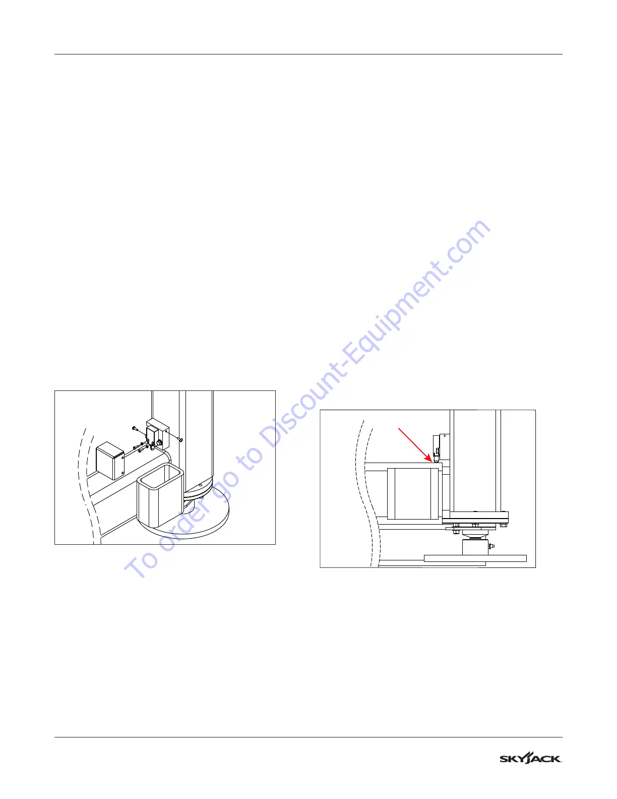
Limit Switch Removal
1. Remove the bolts and washers securing the
upper limit switch/hose cover. Set aside the
hardware and cover for reinstallation later.
2. Remove the screws securing the lower limit
switch cover. Set aside the hardware and cover
for reinstallation later.
3. Remove the washers and screws securing
the limit switch to the mount. Set aside for
reinstallation later.
4. Cut the tie wraps and tape around the split loom
as needed to expose the limit switch cable.
5. Disconnect the applicable wires from the
connector, and cut the ferrules off of the wires
at the end of the cable. Retain the connector for
reuse later.
6. Remove the cable from the split loom. Gently
pull the cable down through the outrigger
weldment, and through the rubber grommet.
Retain the rubber grommet. Discard the old limit
switch and cable.
Limit Switch Replacement
1. Install a new limit switch to the mounting block
using the hardware removed earlier.
2. Feed the new cable through the rubber
grommet, and place the grommet in the hole in
the outrigger weldment.
3. Feed the cable up through the outrigger
weldment, until it comes out the top.
4. Working from top to bottom, adjust the cable
in the split loom and close the split loom by
wrapping electrical tape around it at regular
intervals. Tie wrap the split loom to the hoses.
5. Cut off any unneeded length from the cable, and
strip the end to exposed the wires beneath.
6. Strips the ends from each wire and crimp a
ferrule to each wire end.
7. Insert the wires into the connector end removed
previously. Reconnect the connector.
Limit Switch Adjustment
1. Loosen the bolts securing the mounting block to
the outrigger, and slide the block until the limit
switch plunger is depressed halfway against the
base weldment. Apply a small amount of Loctite
to the bolts, and tighten them.
Limit Switch Testing
1. Turn main power disconnect switch to the ON
position, and start the engine.
2. With the outriggers fully retracted, the unit
should be drivable. With the outriggers extended
more than halfway, the unit should not be
drivable.
To order go to Discount-Equipment.com