MV-32/64 Multiviewer www.snellgroup.com Hardware Configuration
Issue 1 Rev 11 Page 132 © 2014 Snell Limited
D.1.2 Rear connector modules
A variety of rear connector modules are available to suit different signal formats and
interfacing requirements. These may be single width (occupying one card slot), or double
width (occupying two card slots).
D.1.2.1 Summary of rear connector modules
D.1.2.2 Using MV-VIP3 and MV-VIP3D Cards with the MV-RM20 Rear Panel
When the RM20 rear panel is used with the MV-VIP3 or MV-VIP3D cards only inputs 1 and 2
are available for use with Composite video input signals.
SDI and Composite video input signals can be mixed on the MV-RM20 rear panel as long as
the maximum limitation of two Composite video signals (on inputs 1 and 2) is adhered to.
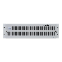
Fig 88. Rear Module Connector Layouts.
RM10 RM200RM20 RM40 RM100
Rear Module
Model Code
Description Rear Width
MV-RM10
3 x YUV/RGB Video Inputs Plus 1 x Y/C (S-Video) with
1 x GPI Input Connector (8 GPI Inputs).
Notes:
• Video Loop card required
• Not compatible with MV-VIP3 & MV-VIP3D cards
Double
MV-RM20
4 x SD-SDI/HD-SDI/Composite Inputs with 1 x GPI Input
Connector (8 GPI Inputs)
Note: MV-VIP3 & MV-VIP3D cards are limited to two inputs
for Composite video (inputs 1 & 2).
Single
MV-RM40
2 x DVI-I plus 2 x SD-SDI/HD-SDI/Composite Inputs.
Notes:
• DVI-I inputs are not compatible with the MV-VIP3 &
MV-VIP3D cards
• This rear has no GPI connector
Single
MV-RM100
4 x SD-SDI/HD-SDI with loop throughs plus 1 x GPI Input
Connector (8 GPI Inputs).
Single
MV-RM200 32 x Analog/Digital Audio Inputs/Output Single
Table 78. Summary of rear connector modules.