MV-32/64 Multiviewer www.snellgroup.com Connection to Other Equipment
Issue 1 Rev 11 Page 82 © 2014 Snell Limited
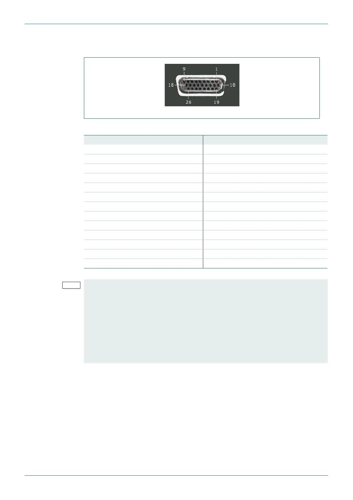
5.1.2 Global GPI Input/Output Connector
Female high density 26 way 'D' connector assignments
The following table gives the pin assignments for the RS GPI Input/Output:
Fig 64. GPI Input/Output Connector.
Pin Number Signal Pin Number Signal
1 GPI-In 2 14 GPI-In 13
2 GPI-In 5 15 GPI-In 16
3 GPI-In 8 16 GPI-Out 2
4 GPI-In 11 17 GPI-Out 5
5 GPI-In 14 18 GPI-Out 8
6 GPI-Out 1 19 GPI-In 3
7 GPI-Out 4 20 GPI-In 6
8 GPI-Out 7 21 GPI-In 9
9 GND 22 GPI-In 12
10 GPI-In 1 23 GPI-In 15
11 GPI-In 4 24 GPI-Out 3
12 GPI-In 7 25 GPI-Out 6
13 GPI-In 10 26 5V (via 0.5A re-settable fuse)
Table 47. GPI Input/Output Connector.
• The MV-32/MV-64 GPI outputs are open collector outputs and require external
pull-up resistors of between 10 k
Ω and 100 kΩ and can sink up to 500 mA. A +5
Vdc out pin is provided on the GPI connector for this purpose.
• For an example of how GPI outputs can be used to drive LEDs, see
section 5.1.2.1.
• The MV-32/MV-64 GPI inputs have weak pull-downs on them and can be driven by
inputs of up to 24 V. The inputs are triggered by inputs above 3 V.
• For an example of how GPI inputs can be used to trigger on-screen tallies, see
section 5.3.