MV-32/64 Multiviewer www.snellgroup.com Installation
Issue 1 Rev 11 Page 22 © 2014 Snell Limited
3.6 Audio I/O connector
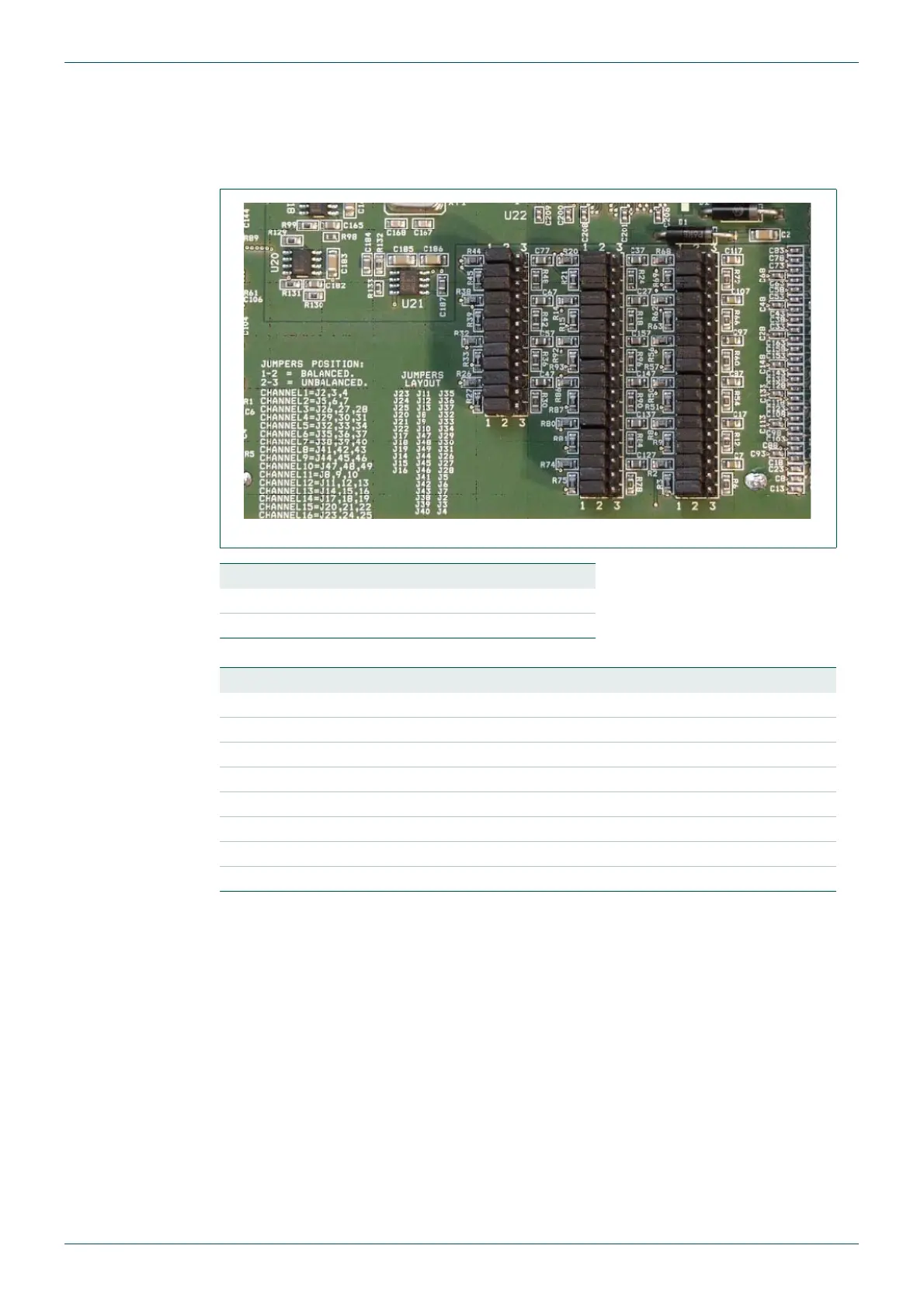
AES/EBU inputs or outputs (depending on the card fitted) may be jumper selected per
channel to be either balanced or unbalanced. These are set from the jumpers on each digital
audio card.
The pin assignment of the connector is given in section 5.1.6.
Fig 9. AES/EBU digital audio input card balanced/unbalanced settings.
Jumper Position Description
1/2 Balanced
2/3 Unbalanced
Table 3. Balanced/Unbalanced Jumper positions.
Channel Jumpers Channel Jumpers
1 J2, J3, J4 9 J44, J45, J46
2 J5, J6, J7 10 J47, J48, J49
3 J26, J27, J28 11 J8, J9, J10
4 J29, J30, J31 12 J11, J12, J13
5 J32, J33, J34 13 J14, J15, J16
6 J35, J36, J37 14 J17, J18, J19
7 J38, J39, J40 15 J20, J21, J22
8 J41, J42, J43 16 J23, J24, J25
Table 4. Jumper numbers for each channel.