MV-32/64 Multiviewer www.snellgroup.com Installation
Issue 1 Rev 11 Page 17 © 2014 Snell Limited
3.3 Connector I/O
The multiviewers use coaxial BNCs for the video inputs, LTC and sync inputs. Microcross
connectors are used for DVI-I inputs and outputs. External audio connections (input or output)
are via female 44 way D-Type connectors, with audio monitoring outputs on a male 25 way
D-Type connector.
The global GPI I/O connector is a high density 26 way female D-Type connector. Local video
card GPI I/O connections are via 15 way female D-Type connectors. There are two USB
connectors on the front panel for keyboard connection and auxiliary functions.
The serial ports comprise a pair of 9 way female D-Type connectors and a pair of standard
RJ45 connectors are provided for LAN connection. The LAN-1 & RS422-1 ports serve the
CPU/Buffer cards fitted in the left of the frame as viewed from the rear panel (the right when
viewed from the front of the multiviewer). The LAN-2 & RS422-2 ports serve the CPU/Buffer
cards fitted in the centre of the multiviewer (MV-32 dual frames only).
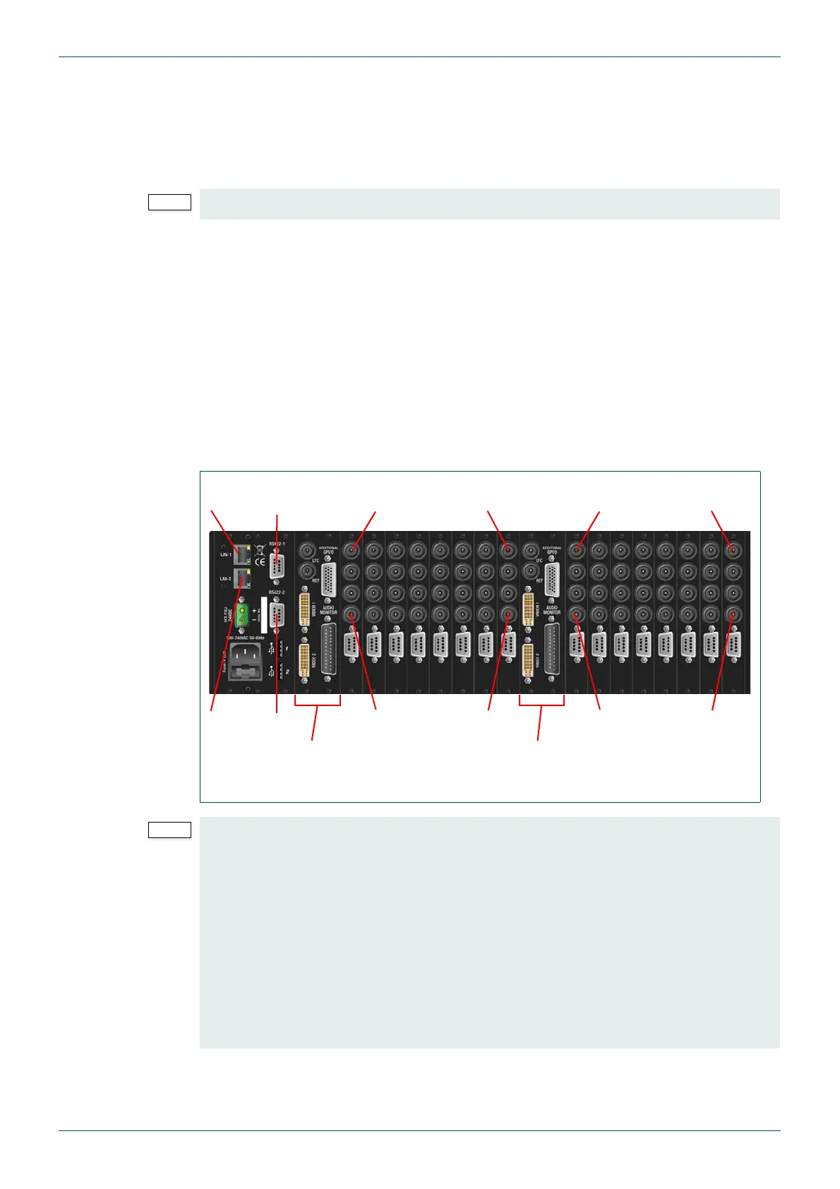
3.3.1 Example: MV-32 Dual Multiviewer Rear Panel Connections
The MV-32 dual multiviewer shown below is fully equipped with single width video rear
panels.
MV-VIP3 and MV-VIP3D cards cannot be used with DVI inputs or Component video inputs.
Fig 4. Example MV-32 Dual Multiviewer 3U Dual Frame Rear Connector I/O.
• If Audio cards are fitted they must be fitted in the slots immediately following the
last populated video card slot, see Appendix D.1.1 for further details.
• Slots 1 and 2 are not compatible with audio cards. If audio cards are installed a
minimum of one video card must be fitted in slot 1 with a loop through rear panel.
This allows the first audio card to be fitted in slot 3.
• When fitted with a second CPU/buffer card slots 13 and 14 are not compatible with
audio cards. If audio cards are installed a minimum of one video card must be fitted
in slot 13 with a loop through rear panel. This allows the first audio card to be fitted
in slot 15.
• Composite video input signals can only be connected to the bottom two BNC
connectors of the rear panel when MV-VIP3 & MV-VIP3D cards are fitted.
Video
Input 4
Video
Input 32
Video
Input 1
Video
Input 29
Video
Input 4
Video
Input 32
Video
Input 1
Video
Input 29
CPU/Buffer Cards
(LAN-1 & RS422-1)
CPU/Buffer Cards
(LAN-2 & RS422-2)
LAN-1, RS422-1
LAN-2, RS422-2