MV-32/64 Multiviewer www.snellgroup.com Installation
Issue 1 Rev 11 Page 23 © 2014 Snell Limited
3.7 Backup Power Supply
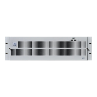
The optional 1U external backup power supply unit (MV-Power) may be installed in 19" bays
and has a depth of approximately 380mm, including connectors. It is designed to be located
close to the MV-32/MV-64 multiviewer frame and is supplied with the necessary
interconnecting DC cable. Up to three supplies can be fitted into the MV-Power but only one is
fitted as standard in the Module B slot (see Fig 10.).
In the event of failure of the internal MV-32/MV-64 multiviewer power supply, MV-Power
provides a backup feed without interruption.
1. Do not mount the backup power supply unit below the MV-32/MV-64 as it restricts
the opening of the MV-32/MV-64 front panel and the cards cannot be
inserted/removed from the MV-32/MV-64. The backup power supply should be
mounted above the MV-32/MV-64.
2. Do Not use any other 24VDC sources or interconnecting cables other than the
MV-Power and supplied cable.
3. The supplied 25 way D-type shell MUST be fitted into the 25 way (CN500)
connector on the rear of the backup power supply for the DC output to be active.
4. The supplied 25 way D-type shell is pre-wired to ensure that any power supply
modules fitted in the MV-Power will be active. If this is misplaced another can be
produced by connecting pin 21 to pin 1, to pin 8 and to pin 15 (see Table 6. for
details).
Fig 10. MV-Power Backup Power Supply without facia and with a single PSU Module
fitted.
Fig 11. The 1U MV-Power Backup Power Supply rear panel.
CN500
Connector
+Ve and -Ve
Connectors
Mains IEC Inputs for
power supply
modules A, B and C
CAB
Address
Switch
Not Used