MV-32/64 Multiviewer www.snellgroup.com Connection to Other Equipment
Issue 1 Rev 11 Page 86 © 2014 Snell Limited
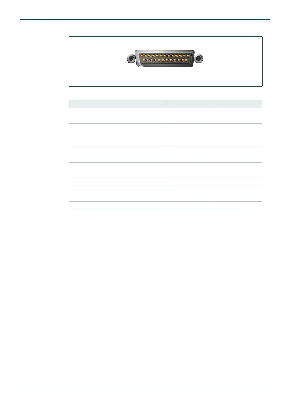
5.1.7 Analog Monitor Out Connector D-sub 25 Male
The following table gives the pin assignments for the 25-pole sub-D male connector.
5.2 Configuring the MV-32/MV-64 for TSL UMD Protocol
This section describes the procedure for configuring UMDs. The steps repeat some
information that is in other sections of this manual.
The TSL protocol uses display addressing to select the UMD to update. In the MV a display
address refers to an input number. TSL address 0 refers to MV input 1, TSL address 1 refers
to MV input 2 etc.
The software settings that are essential for getting the UMD working are:
• Putting the serial port into TSL UMD mode and setting its baud rate
• Ensuring that line 1 is turned on for the UMDs
1. Check that the MV-32/MV-64 matches the TSL controller serial port type. Use the
MV-32/MV-64 jumpers to set the serial port to either RS232 or RS422 to match the
TSL controller. Ensure the MV-32/MV-64 serial port is set to normal mode rather than
debug mode. See section 3.5 for information on the MV-32/MV-64 jumper settings.
Fig 67. Analog Monitor Out Connector D-sub 25 Male.
Pin Number Signal Pin Number Signal
1 In 8+ 14 In 8-
2 In 8GND 15 In 7+
3 In 7- 16 In 7GND
4 In 6+ 17 In 6-
5 In 6GND 18 In 5+
6 In 5- 19 In 5GND
7 In 4+ 20 In 4-
8 In 4GND 21 In 3+
9 In 3- 22 In 3GND
10 In 2+ 23 In 2-
11 In 2GND 24 In 1+
12 In 1- 25 In 1GND
13 -
Table 52. Analog Monitor Out Connector D-sub 25 male.