MV-32/64 Multiviewer www.snellgroup.com Connection to Other Equipment
Issue 1 Rev 11 Page 83 © 2014 Snell Limited
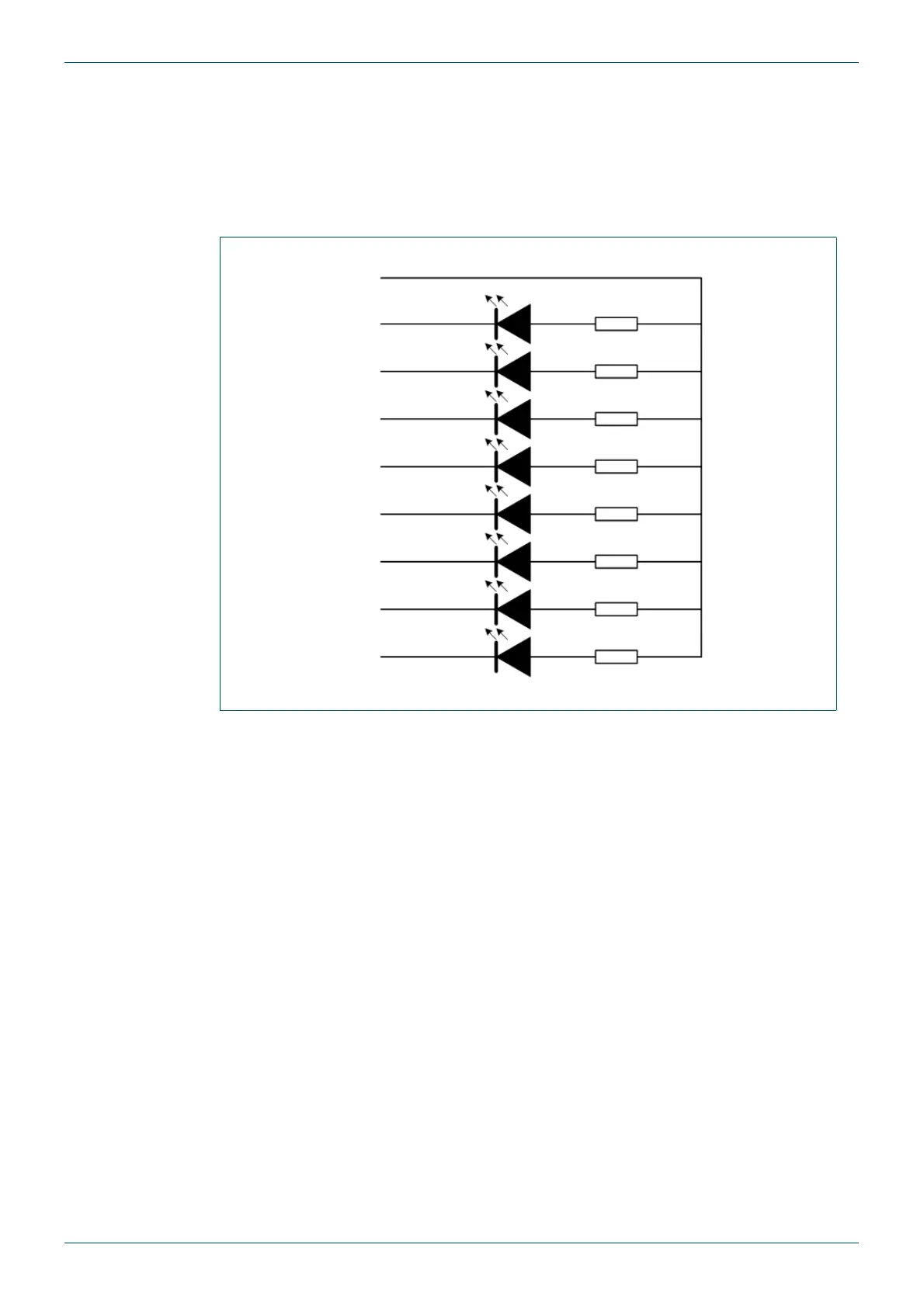
5.1.2.1 Example: Using LEDs on the GPI Outputs
The GPI outputs on the MV-32/MV-64 are open collector drivers. There is a 5 Vdc pin to
provide the power needed to drive LEDs or relays.
The following schematic is an example of the wiring needed when an LED is to be driven by
each output. The numbers on the left are the GPI output numbers and pin-numbers for the
outputs on the 26 way female D-Type connector on the rear of the MV-32/MV-64.
Fig 65. LEDs on the GPI Outputs
150 Ω
150 Ω
150 Ω
150 Ω
150 Ω
150 Ω
150 Ω
150 Ω
+5 Vdc
GPI Out 1
GPI Out 2
GPI Out 3
GPI Out 4
GPI Out 5
GPI Out 6
GPI Out 7
GPI Out 8
Pin 26
Pin 6
Pin 16
Pin 24
Pin 7
Pin 17
Pin 25
Pin 8
Pin 18