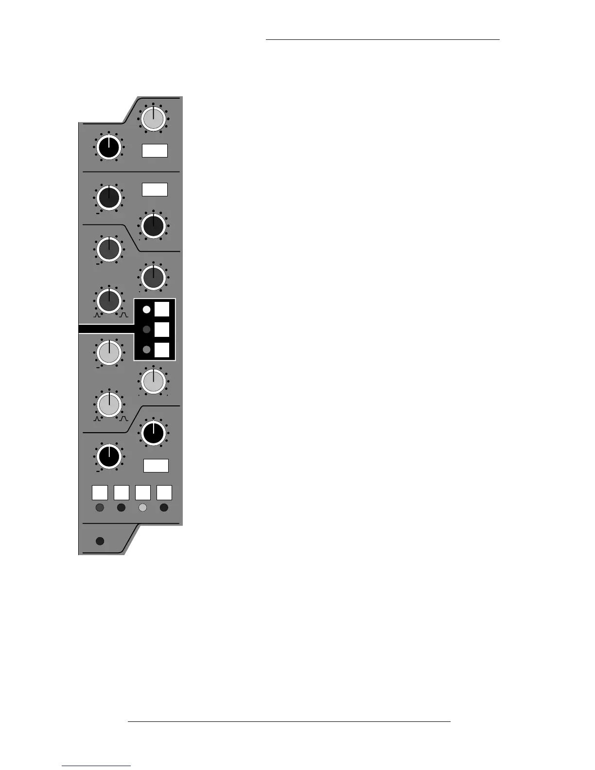
Filters
The Filters can be completely bypassed when the controls are
turned fully anti-clockwise to the detented OUT position.
The High pass filter has a slope of 18dB per Octave and the
Low pass filter has a slope of 12dB per octave.
Overload Indicator
The overload circuit monitors the signal in the Channel path at
three different points. The level at which it lights can be
adjusted from the centre section between +18dBu and +24dBu
in 1dB steps. (See the SL9000J Service Manual for more details.)
The monitor points are: post-channel fader, post-insert point
and channel input pre any signal processing.
Insert Point
The insert point is switchable PRE or (normally) post the EQ
and before the fader. The Insert Send jack (Row E) always
carries the channel signal and is normalled down to the Insert
Return jack (Row F). The IN button switches the return back
into the signal path, hence switching in any device patched to
the insert jacks.
The insert IN button is automated. See the J Series Computer
Operator’s manual for more details.
The Insert Return can also be used as a key input to the
dynamics. Selecting KEY re-routes the insert return to feed the
dynamics side chain. See also Dynamics Section, Page 3-3.
SL 9000 J Console Operator’s Manual
3-8
22.12.94
BELL
BELL
IN
MON E