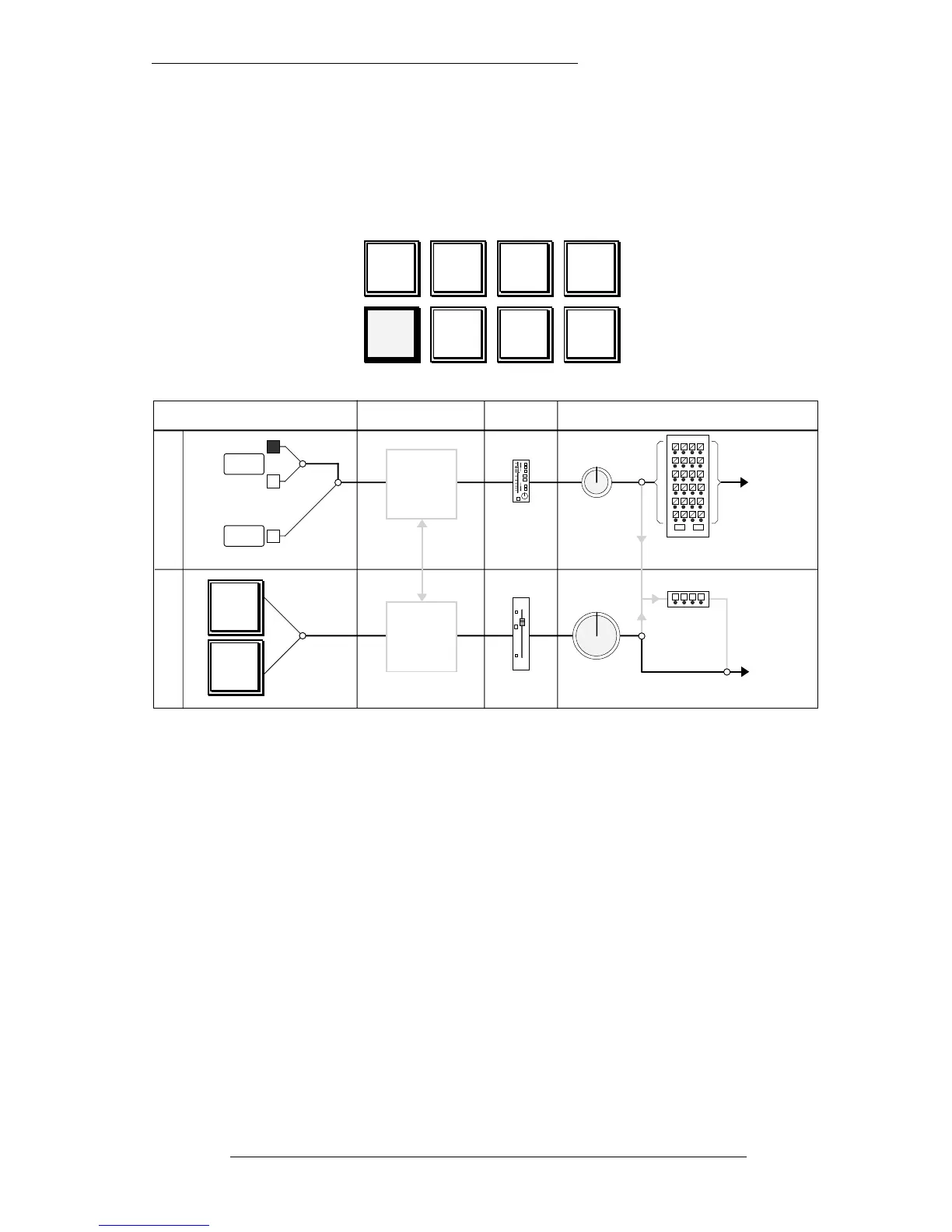
Record Status
Recording basic tracks onto a blank multitrack tape is the starting point! In the record
mode, with the RECORD status button selected, the various elements in the module
signal paths are connected as shown below.
This will be the preferred recording mode for most engineers. If you have previously
been using an SL4000 system, note that RECORD status on the SL9000 is equivalent to
RECORD + VCA to MONITORS (FADER REVERSE on Ultimation and G+ consoles)
status.
The Large Faders are much more useful if used as monitor faders during recording, as
they can, if required, be automated for end-of-the-day monitor mixes.
The upper section of the diagram shows the ‘Channel’ signal path whilst the lower
part shows the ‘Monitor’ signal path. The Channel signal path is that path which
originates from the Channel Input section of the I/O module. The Monitor signal is
derived from the Monitor Input section.
Basic Routing and Signal Flow
2-5
5.9.96
1-48
Routing
C
H
A
N
N
E
L
M
O
N
I
T
O
R
INPUT SELECTION PROCESSING FADER OUTPUT ASSIGNMENT
RL
C
Small
Fader
Small
Fader
Pan
C
ODD EVEN
To
Bus Trims
and
Tracks
EQ
Filters
Dynamics
LINE
MIC
EQ
Filters
Dynamics
Large
Fader
10
5
0
5
10
20
30
40
50
Large
Fader
Pan
C
LR
Stereo
Subgroups
ABCD
To
Main Mix
Busses
MASTER
READY
GROUP
MASTER
INPUT
FLIP
SMALL
FADER
TO MON
RECORD REPLAY MIX
STATUS
LOCK
TAPE
GROUP
FLIP
SUB GP