Channel Meter Controls
The switches in the CHANNEL METERS bank have the following functions:
PPM – Selects Peak Meter scale and ballistics. The peak scale is a fast attack (100µSec)
design, intended for use with both analogue and digital recorders. It is scaled from
0dB to -52dB. A reading of ‘0’ normally corresponds to an input level of +18dBu – ie.
6dB below the digital clipping point on most professional digital recorders.
The Peak meter can be calibrated from a computer terminal to read ‘0’ over the range
+16dBu to +24dBu.
A single segment, which holds for 2 seconds, gives an indication of peak levels.
VU – Selects VU scale and ballistics. A reading of 0VU normally corresponds to a level
of +4dBu but this can be changed from a terminal to give a reading of 0VU over the
range 0dBu to +6dBu.
A single segment, which holds for 2 seconds, gives an indication of peak levels.
STORE PEAK – The peak level reaching each meter is stored whenever this button is
pressed.
DISPLAY PEAK – When selected, the peak levels stored by the STORE PEAK button
are displayed as a single segment which does not decay. This peak reading is updated
as long as the STORE PEAK button is still selected.
Note that selecting DISPLAY PEAK in VU mode will turn on both Peak and VU meter
scales. The peak segment is a true peak level and is shown against the Peak scale.
CLEAR PEAK – Clears the stored peak readings.
SL 9000 J Console Operator’s Manual
5-16
21.12.94
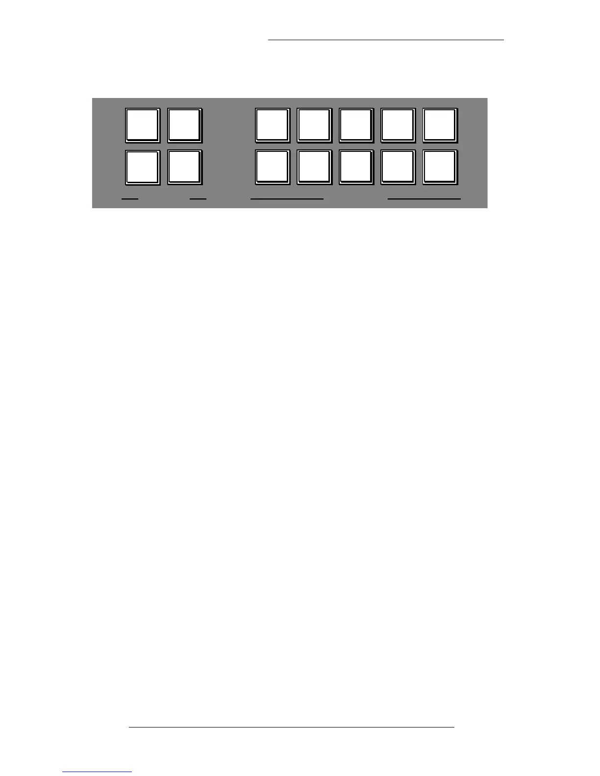
MAIN METERS CHANNEL METERS
DESK
OUTPUT
FOLLOW
MONITOR
EXT 1 EXT 2
STORE
PEAK
DISPLAY
PEAK
CLEAR
PEAK
CAL
METERS
VU PPM
LF
MIX
SF
MIX
METER
INPUT
C/SECT
SELECT