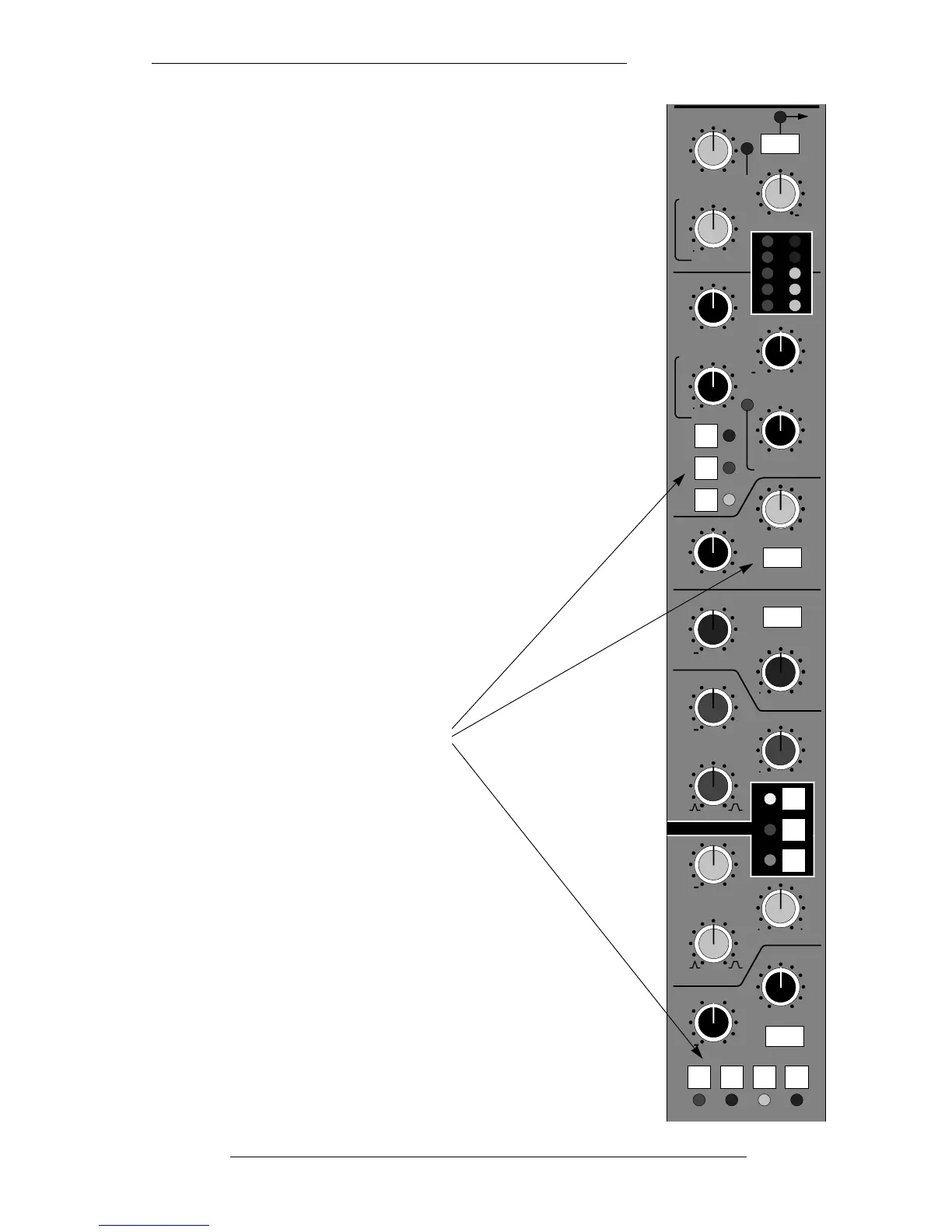
Signal Processor Routing
Each SL911J Input/Output module contains three separate
signal processing devices:
• The 4-band Parametric Equaliser
• The High and Low Pass Filters
• The Dynamics Section
comprising a compressor/limiter
and expander/gate.
These processors can be used in either the Channel or the
Monitor signal paths. Seven buttons are used to determine
where each processor will be placed in the signal chain.
Diagrams on the following pages show the various possible
combinations.
Signal Processor Routing
4-1
22.12.94
BELL
BELL
IN
MON E
CH
IN
CH
OUT
MON
DYN SC
SPLT
LINK
IN
KHz
dB
HMF
dB
Q
KHz
LMF
dB
Q
KHz
LF
dB
Hz
+
+
0
1 5 16
67
+
2 2 5
0
+
0
30 450
RATIO
20
14
10
6
3
DYNAMICS
PK
Pull
THRESHOLD
RELEASE
THRESHOLD
RANGE
RELEASE
HOLD
Pull for fast attack
Pull for fast attack
Pull for EXP
1
0
0
0
+10 20
1 4
0 40
30 +10
0
14
0 4
KHz
FILTERS
Hz
HF
OUT
350
3
OUT
INSERT
KEY
PRE
0
EQ
Processor Routing Buttons