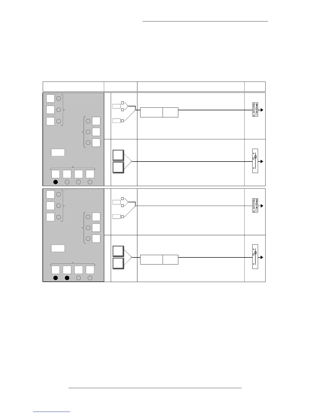
The first two examples show that the Equaliser and Filters are normally treated as a
single unit, which may be switched into either the Channel or Monitor path. All these
diagrams show input and fader selections for the RECORD status. Note that the
Channel Input Section always feeds the Channel signal path and the Monitor Input
Section always feeds the Monitor signal path.
Note that the Filters normally follow the Equaliser, but see opposite page. The E
button is used to select alternative parameters for the EQ, and has no effect on the
position of the EQ in either signal path.
As well as the MON button, the EQ IN button must also be pressed to switch the EQ
into circuit in the Monitor path. This represents a change from the SL4000, caused by
the fact that the EQ IN button is automated and the EQ may be switched in or out of
both the Channel and Monitor paths under computer control.
SL 9000 J Console Operator’s Manual
4-2
13.9.94
C
H
A
N
N
E
L
M
O
N
I
T
O
R
Small
Fader
Large
Fader
10
5
0
5
10
20
30
40
50
IN
MON ESPLT
EQ
CH
IN
CH
OUT
MON
DYN SC
DYNAMICS
IN
KEY
PRE
INSERT
EQUALISER
FILTER
LINE
MIC
FLIP
SUB GP
TAPE
GROUP
INPUT SIGNAL PROCESSOR PLACEMENT FADERPROCESSOR SWITCHING
4 BAND
EQUALISER
Hi & Lo
FILTERS
C
H
A
N
N
E
L
M
O
N
I
T
O
R
Small
Fader
Large
Fader
10
5
0
5
10
20
30
40
50
IN
MON ESPLT
EQ
CH
IN
CH
OUT
MON
DYN SC
DYNAMICS
IN
KEY
PRE
INSERT
EQUALISER
FILTER
LINE
MIC
FLIP
SUB GP
TAPE
GROUP
4 BAND
EQUALISER
Hi & Lo
FILTERS