Oscillator
The oscillator section (see right) contains controls for frequency, level and routing of
the oscillator to the Main outputs, the Stereo Subgroup outputs and the Multitrack
Group outputs.
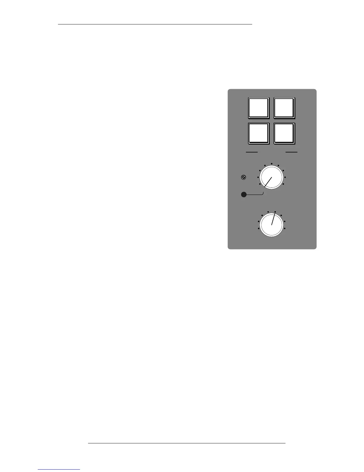
BUSSES 1-48 – Routes the oscillator to all multitrack
Group outputs.
MIX – Routes the oscillator to the main LCRS outputs.
A B C D – Routes the oscillator to the four Stereo
Subgroup outputs.
ON - Switches the oscillator on, would you believe. It’s
good practice to turn the oscillator off when recording,
to prevent any leakage onto the desk outputs.
The rotary FREQ switch provides eight preset
frequencies. The LEVEL control adjusts the output
level from -25dB to +20dB. When fully anticlockwise, a
preset level is selected which can be calibrated with
the small multiturn pot located to the left of the main
level control. A red LED lights to show when the level
control is no longer in the calibrated position.
The oscillator output is available on the patch (jack N9) and is normalled to the tone
distribution system (P9). This allows an external oscillator to be fed into the tone
routing switches – very useful for injecting those odd frequencies or for pink (or red!)
noise.
A second output, 60dB lower than main oscillator output, is available on jack N10 for
testing microphone inputs etc.
The Centre Section
5-23
21.12.94