The Patch
The SL 9000 J Series patchbay is supplied with a minimum of nine, 1U (rack unit) high,
panels of bantam (TT) mini-jacks, each with two rows of jacks.
Each row will contains a different number of jacks according to the number of I/O
modules in the console. Consoles with more than 56 channels come with the patch
split into two columns, ie. two columns of 32-wide rows for a 64 channel console, two
columns of 40-wide rows for an 80 channel console etc. The majority of consoles are
supplied with integral patchbays, however, as an option, versions with remote
patchbays are available. The layout and normalling of a remote patchbay will be the
same as that for an integral one of the same size.
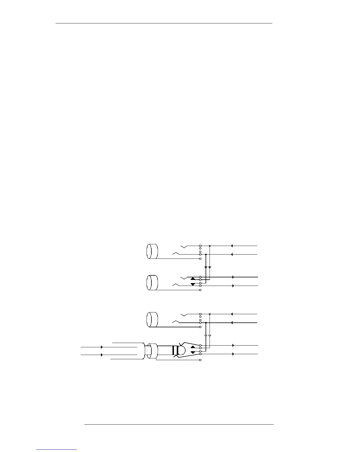
The rows in each patch panel comprise a logical pair, the upper jack being an output
feed and the lower jack being an input. There are two types of normalling used within
the patch:
HALF-NORMALLED – The top row is an output listen (bridging) jack. If a jack is
inserted into the top row it receives the feed on that socket but does not break the
normalling to the row below. The outers are wired down to the inners (blades) of the
row below. The bottom row is an input jack and when a patchcord is inserted, it breaks
away the normalled feed from the row above.
The Patch
6-1
15.9.94
Balanced Feed
Top Row - Listen/Output Jack
Bottom Row - Break/Input Jack
Hot
Cold
Tip - Hot
Ring - Cold
When a plug is inserted it breaks away the
feed from the jack above and sends the
signal on the plug to the INPUT.
The signal coming to
the top listen jack
is normalled to the
bottom input.
FROM
OUTPUT
TO
INPUT
FROM
OUTPUT
TO
INPUT