Metering
Centre Section Meters
Fitted above the SL952/953 master panels are either four VU meters and an LCD
phase ‘scope or five VU meters, a phase meter and two indicator panels. In either case,
four of the VU meters are dedicated to reading the LCRS meter outputs from the
centre section.
If fitted, the phase ‘scope is fed by the left and right meter outputs.
If fitted, the fifth VU meter is fed by a mono sum of the other four meter outputs, and
the phase meter by left and right meter outputs. The two indicator panels provide
LED tallies showing the state of the monitor Cut and Dim switches, whether Solo is
selected, whether the SLS output is un-muted, and whether the Listen Mics are on.
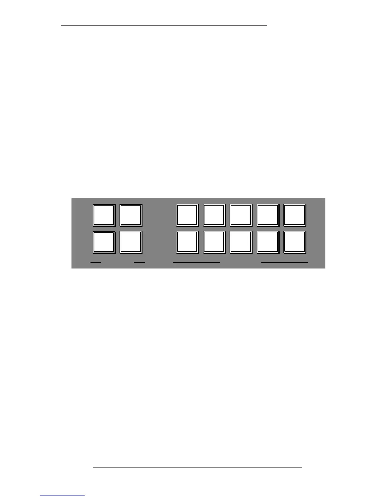
Four MAIN METERS buttons assign signals to these meters:
DESK OUTPUT – Selects the Main LCRS output to the main meters.
FOLLOW MONITOR – Whatever signal has been selected to the monitor
loudspeakers will be displayed on the main meters.
EXT 1 – The main meters will display the level of an external source selected on
External Source Selector 1, irrespective of whether it is being monitored or not. In
other words, the console’s main output can be monitored while the meters are used to
check the returns from a stereo tape machine recording the desk output.
EXT 2 – The main meters will display the level of an external source selected on
External Source Selector 2, irrespective of whether it is being monitored or not.
A bank of eight LCD meters is fitted above the computer monitor. The C/SECT
SELECT switch, in the CHANNEL METERS bank of switches toggles the source for
these meters between the four Stereo busses, the eight Auxiliary busses and the Main
LCRS meter feeds. On some consoles the remaining four meters, when LCRS is
selected, are fed from the patch. This allows, for example, master machine returns to
be metered next to the desk output.
The Centre Section
5-15
22.12.94
MAIN METERS CHANNEL METERS
DESK
OUTPUT
FOLLOW
MONITOR
EXT 1 EXT 2
STORE
PEAK
DISPLAY
PEAK
CLEAR
PEAK
CAL
METERS
VU PPM
LF
MIX
SF
MIX
METER
INPUT
C/SECT
SELECT