Wave User Manual 13
Version 4
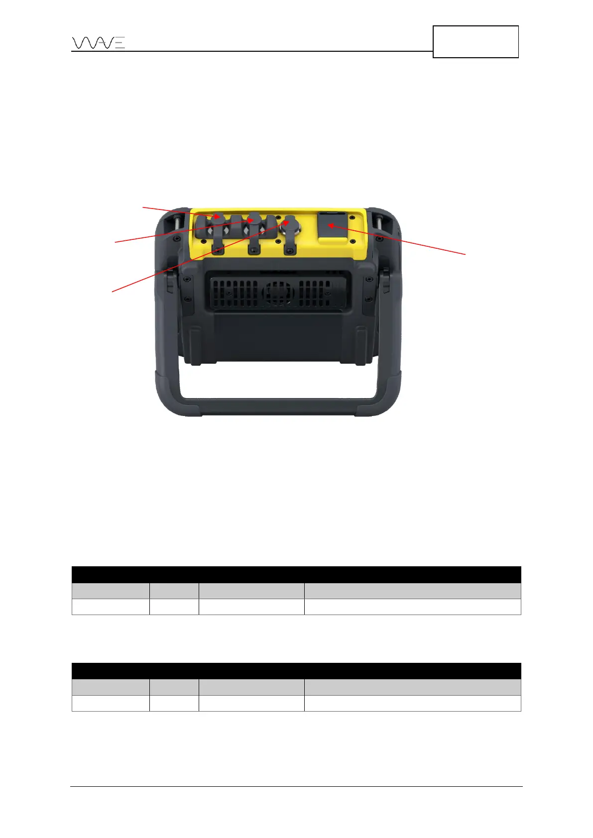
3.4 The UT Connectors
The UT connectors are located on top of the unit. There is one TX/RX connector and one
RX connector. They are identified directly on the casing. These UT connectors can be
LEMO or BNC.
When using the instrument in pulse-echo mode, only the TX/RX output is used. For pitch
and catch, both TX/RX and RX must be hooked up to the probe.
Figure 4 – Wave connectors and the expansion ports
3.4.1 The UT Connector Pinouts
The following tables describe the pinouts of the UT connectors. Figure 5 and Figure 6
illustrate the localisation of the pinouts in the Lemo connector and BNC.
Table 1 – TX/RX connector pinouts