60 Wave User Manual
Version 4
You can add up to 16 points to a DAC curve and also have four Split DACs, depending on
their needs.
View the following video for how to create a DAC curve.
12.2.2 DAC Sizing Options
Once a DAC curve is created, these are the following sizing options available for the DAC
sizing method.
Table 21 – DAC sizing options
The transfer loss is the gain to compensate for the difference of
attenuation between a reference standard and the part to be
inspected.
It sets the trigger of the alarm when DAC curve is on (DAC, G1, 6 dB, 0
dB, -2 dB, -6 dB, -10 dB, -12 dB and -14 dB). Options are directly
dependent on DAC sub curves.
Turns on/off Split DAC option
-2/-6/-10, -6/-14, JIS and Custom
12.2.3 Absolute and Relative DAC Gain Mode
Under sizing options, the DAC curve height can be displayed in two different ways. To
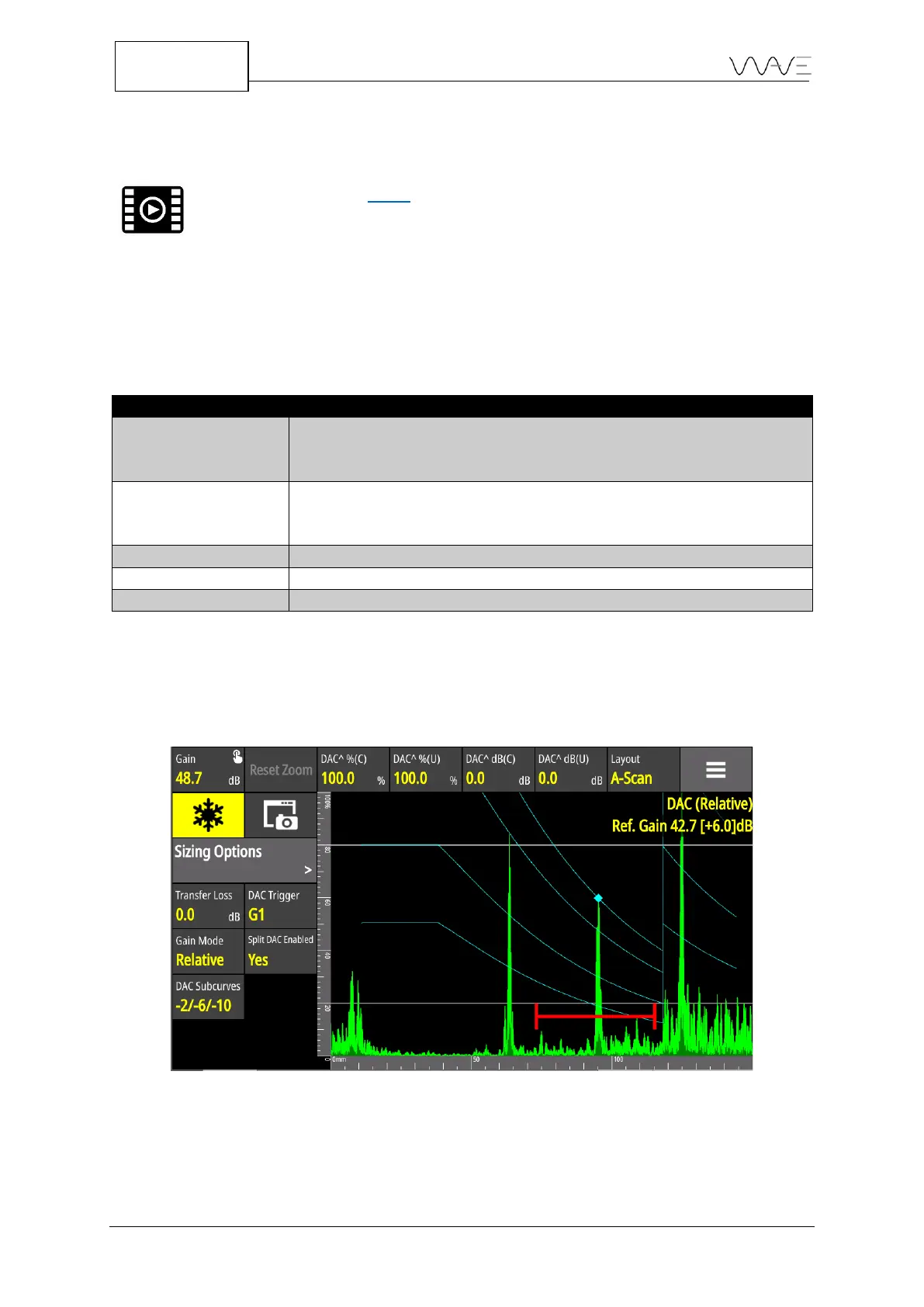
dynamically adjust its height, set the Gain Mode to Relative.
Figure 42 – Gain mode set to Relative and 6 dB of scanning gain has been added
In the figure above, 6 dB of scanning gain has been added. All the DAC curves have also
been increased by 6 dB. Please noted that all relative amplitude measurements have not
changed ( +0 dB ).