14 Wave User Manual
Version 4
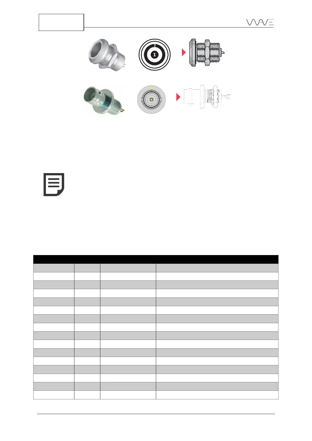
Figure 5 – Lemo ultrasound connector pinouts
Figure 6 – BNC ultrasound connector pinouts
3.5 The GPIO Connector
An additional connector is present just beside the UT connectors. This is the GPIO
connector for encoder inputs and digital outputs namely used for alarms.
NOTE: The UT and GPIO connectors, when not used, should always
be hidden by their protective covers. Though these connectors are
rugged and rated IP67, they can eventually become damaged by the
accumulation of dirt, which may cause some contacts to fail.
3.5.1 GPIO Connector Pinout
The following table describes the pinouts of the GPIO connector. Figure 7 illustrates the
localisation of these pinouts.
Table 3 – GPIO connector pinouts
5V DC power supply (500 mA limit)
Alarm Output 1 / General Purpose Output 1
Alarm Output 2 / General Purpose Output 2
Alarm Output 3 / General Purpose Output 3
Alarm Output 4 / General Purpose Output 4
Noninverting Receiver Input and Driver Output
Inverting Receiver Input and Driver Output