56 Wave User Manual
Version 4
11 The Scan Plan View
The Scan Plan View allows you to see the part with the probe and the distances. Of
course, it is possible to add visual elements such as welds, real A-scan ray tracer and grids.
The Scan Plan View is the visual tool that allows a better understanding of defects in an
inspected part.
11.1 Scan Plan Menu
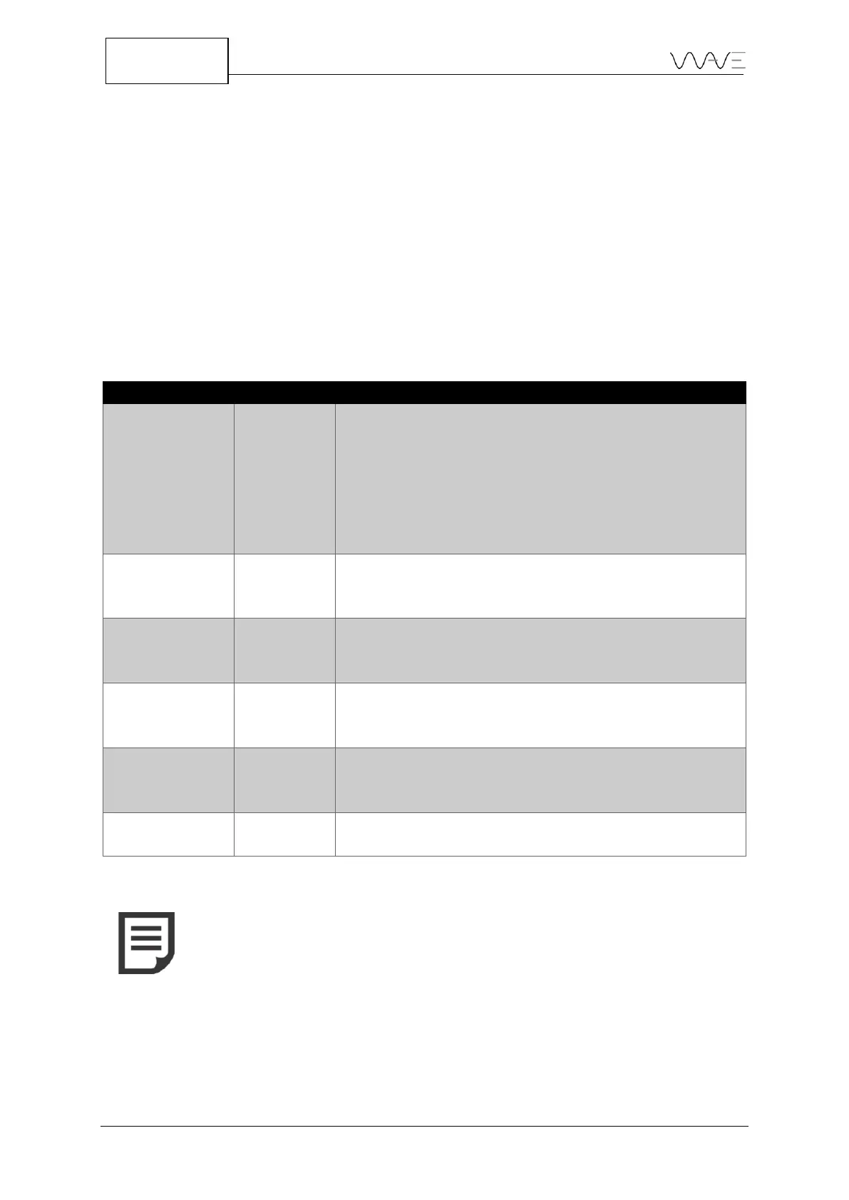
The following options are available in the Scan Plan menu.
Table 20 – Scan Plan parameters and their meanings
For T-joint or Corner joint: The linear distance from
the vertical wall thickness to the point where the beam
exits the wedge.
For Flat and Curved parts: The linear distance from
point 0 to the point where the beam exits the wedge.
By default, this distance is set as -20.00 mm for all
geometries.
Rulers are located on the left and on the bottom axis
and can show metric/imperial values depending on the
unit system.
By default, the dimensions are 10x10mm (1”x1”),but
can change as you zoom in or out. Grid lines may help
you on sizing and distance evaluation.
This feature allows you to see the weld overlay. It helps
you to be more confident with defects location and
evaluation.
This feature allows you to have the A-scan displayed
over the ray tracer, in real time. It helps you to be more
confident with defects location and evaluation.
It allows you to show or hide the distance.
NOTE: Distances located on the left side of the vertical reference
point (Y axis origin) are set by default as negative values. Distances
located on the right side of the vertical reference point (Y axis origin)
are set by default as positive values.