Wave User Manual 47
Version 4
8.4 Gate Advanced Settings
This section presents slightly more advanced features for the gates.
8.4.1 Gate Polarity
The Gate Polarity parameter may take the following values: absolute, positive or
negative. Here is a brief description of each:
● Absolute: Considers all signal for evaluation (available only with non-rectified
signal)
● Positive: Considers only the positive signal for evaluation (available with non-
rectified or rectified or positive only signal)
● Negative: Considers only the negative signal for evaluation (available only with
non-rectified or negative only signal)
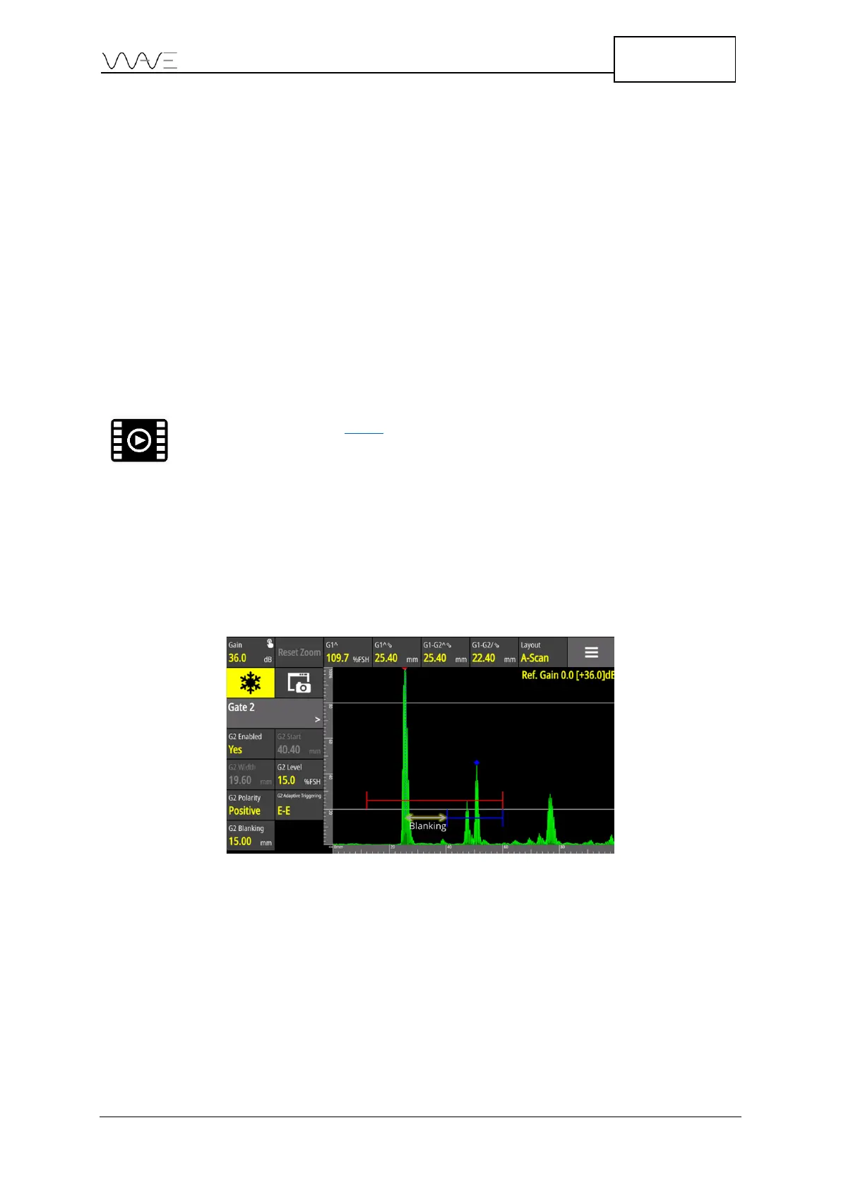
8.4.2 Setting up an Adaptive Gate in Gate Mode
Gate 2 and Gate 4 have an adaptive triggering feature. This feature adapts the gate with
respect to the start function (Gx Start) of G1^ peak position. In the example below, G1
Start is set at 12 mm. The G1^ sound path is 25.4 mm. The blanking value is the minimum
offset between G1^ and G2 Start. In this case, the G2 Blanking is set to 15 mm. Hence,
the G2 Start will automatically be set to (12 mm + 25.4 mm +15 mm = 40.4 mm).
Figure 34 – Adaptative gate
For a gate adaptive triggering set to F-F, it has the same described behaviour. However,
but the flank is the new source of position.
In echo to echo mode, this prevents Gate 2 to trigger the same peak as Gate 1.
Consequently, a G2-G1 measurements would have been set to 0 mm.